program prior to the interrupt (by unstacking the previous
CPU
state). Unlike
li'ESEf,
hardware
interrupts do not cause the current instruction execution to
be
halted, but
are
considered pending
until the current instruction execution
is
complete.
When the current instruction
is
complete, the processor checks
all
pending hardware interrupts and
if unmasked, proceeds with interrupt processing; otherwise the next instruction
is
fetched and
ex-
ecuted. Note that masked interrupts are latched for later interrupt service.
If both
an
external interrupt and a timer interrupt are pending at the end
of
an
instruction execution,
the external interrupt
is
serviced first. The SWI
is
executed
as
any other instruction.
NOTE
The timer and INT2 interrupts share the same vector address. The interrupt routine must
determine the source by examining the interrupt request bits
(TCR
b7
and M R
b7).
Both
TCR
b7
and
MR
b7
can
only
be
written to zero by software.
The external interrupt,
TNT
and
fI\JT2,
are synchronized and then latched
on
the falling edge of the
input
signal. The INT2 interrupt
has
an
interrupt request bit (bit
7)
and a
mask
bit (bit
6)
located
in
the miscellaneous register (MRl. The INT2 interrupt
is
inhibited when the mask bit
is
set. The INT2
is
always
read
as
a digital input on port
D.
The
fI\IT2
and timer interrupt request bits, if set, cause the
MCU to process
an
interrupt when the condition code I bit
is
clear.
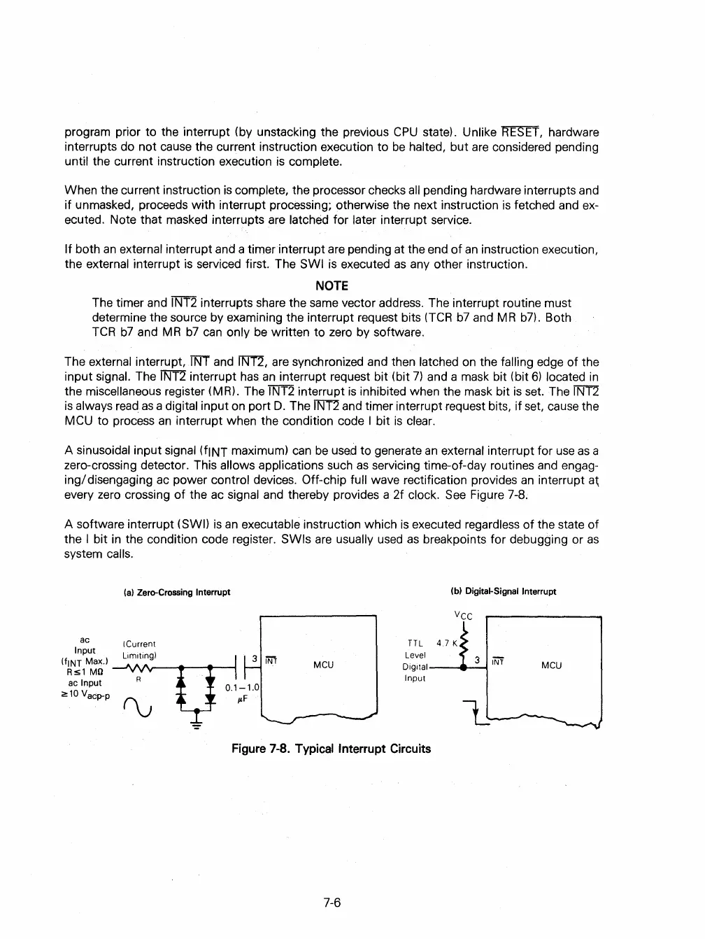
A sinusoidal input signal (fINT maximum)
can
be
used
to generate
an
external interrupt for
use
as
a
zero-crossing detector. This
allows applications such
as
servicing time-of-day routines
and
engag-
ing/
disengaging
ac
power control devices. Off-chip full wave rectification provides
an
interrupt
a~
every zero crossing of the
ac
signal and thereby provides a 2f clock.
See
Figure 7-8.
A software interrupt
(SWI)
is
an
executable instruction which
is
executed regardless
of
the state of
the
I bit
in
the condition code register. SWls
are
usually
used
as
breakpoints for debugging or
as
system calls.
ac
Input
(a)
Zero-Crossing Interrupt
ICurrent
(tINT Max.l ---'\Af'v---..-
.....
---I
Rs1
MO
ac Input
~10
Vacp-p
MCU
(b) Digital-Signal Interrupt
Vcc
TTL
4.7 K
Level 3
iNf
Digilal--
.....
--I
Input
lJ
MCU
Figure
7-8.
Typical
Interrupt
Circuits
7-6
 Loading...

