becomes the input to the timer. The external TIMER pin can, in this mode, be used
to
count exter-
nal
events
as
well
as
external frequencies for generating periodic interrupts.
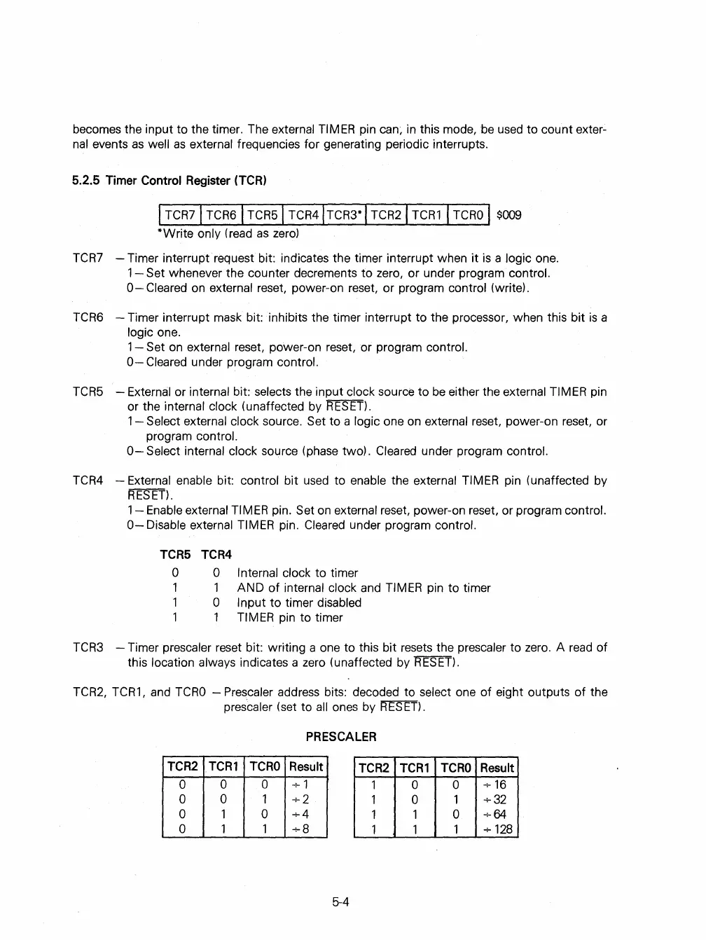
5.2.5
Timer
Control
Register
(TCR)
I
TCR
7
1
TCR6\
TCR51
TCR41
TCR3* I TCR21
TCR1
I
TCRO
I
$009
*Write only (read
as
zero)
TCR7
- Timer interrupt request bit: indicates the timer interrupt when
it
is
a logic one.
1-
Set whenever the counter decrements to zero, or under program control.
0-
Cleared
on
external reset, power-on reset, or program control (write).
TCR6
- Timer interrupt
mask
bit: inhibits the timer interrupt to the processor, when this bit
is
a
logic one.
1 -
Set
on
external reset, power-on reset, or program control.
0-
Cleared under program control.
TCR5
- External or internal bit: selects the input clock source to
be
either the external TIMER pin
or the internal clock (unaffected by
RESET).
1 - Select external clock source. Set to a logic one
on
external reset, power-on reset, or
program
control.
0-
Select internal clock source (phase two). Cleared under program control.
TCR4
- External enable bit: control bit
used
to enable the external TIMER pin (unaffected by
RESET).
1-
Enable external TIMER pin. Set
on
external reset, power-on reset, or program control.
0-
Disable external TIMER pin. Cleared under program control.
TCR5
o
1
1
1
TCR4
o
1
o
1
Internal clock to timer
AND
of
internal clock and TIMER pin to timer
Input
to
timer disabled
TIMER pin to timer
TCR3
- Timer prescaler reset bit: writing a one to this bit resets the prescaler to zero. A
read
of
this location always indicates a zero (unaffected by
RESET),
TCR2,
TCR1,
and
TCRO
- Prescaler address bits: decoded to select one of eight outputs
of
the
prescaler (set to
all
ones by
RESET),
PRESCALER
TCR2
TCR1
TCRO
Result
TCR2
TCR1
TCRO
Result
0
0
0
+1
1
0 0
+16
0
0
1
+2
1 0
1
+32
0 1 0
+4
1
1
0
+64
0 1 1
+8
1 1
1
+
128
5-4
 Loading...

