English
Operation manual
19
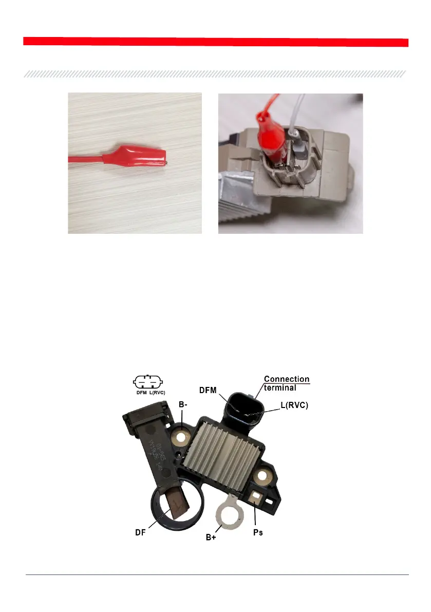
Figure 18 - Connection of cable clips to the contacts in the terminals
When the connection is made, press «OK» - the tester will automatically switch over to the test
mode appropriate for the tested voltage regulator. Then, proceed to the voltage regulator testing
(the process is described below).
If the information on the markings of the voltage regulator terminals cannot be found in the
database, research online. Appendix 3 is yet another source of information. There you can find
connection diagrams of the most common voltage regulator types. Use the diagram with terminal
markings found online and the examples below to connect the diagnostic cable.
Figure 19 shows a diagram (an example) for connection of voltage regulator ARE1054.
Figure 19 - Voltage regulator ARE1054