English
Tester MS016
20
Identify the type of the voltage regulator by the terminal contacts shown in Fig.19 and use
information set out in Appendices 1, 2 of the actual Instruction. Shown here are terminals DFM
and L(RVC) (can also be marked as L(PWM)). By terminal L (RVC) we identify this voltage regulator
as RVC type.
Then, using Appendix 1, we determine which clips (connectors) of the diagnostic cable must be
connected to the voltage regulator. A diagram of voltage regulator ARE1054 connection to the
tester is shown both in Table 2 and Figure 20.
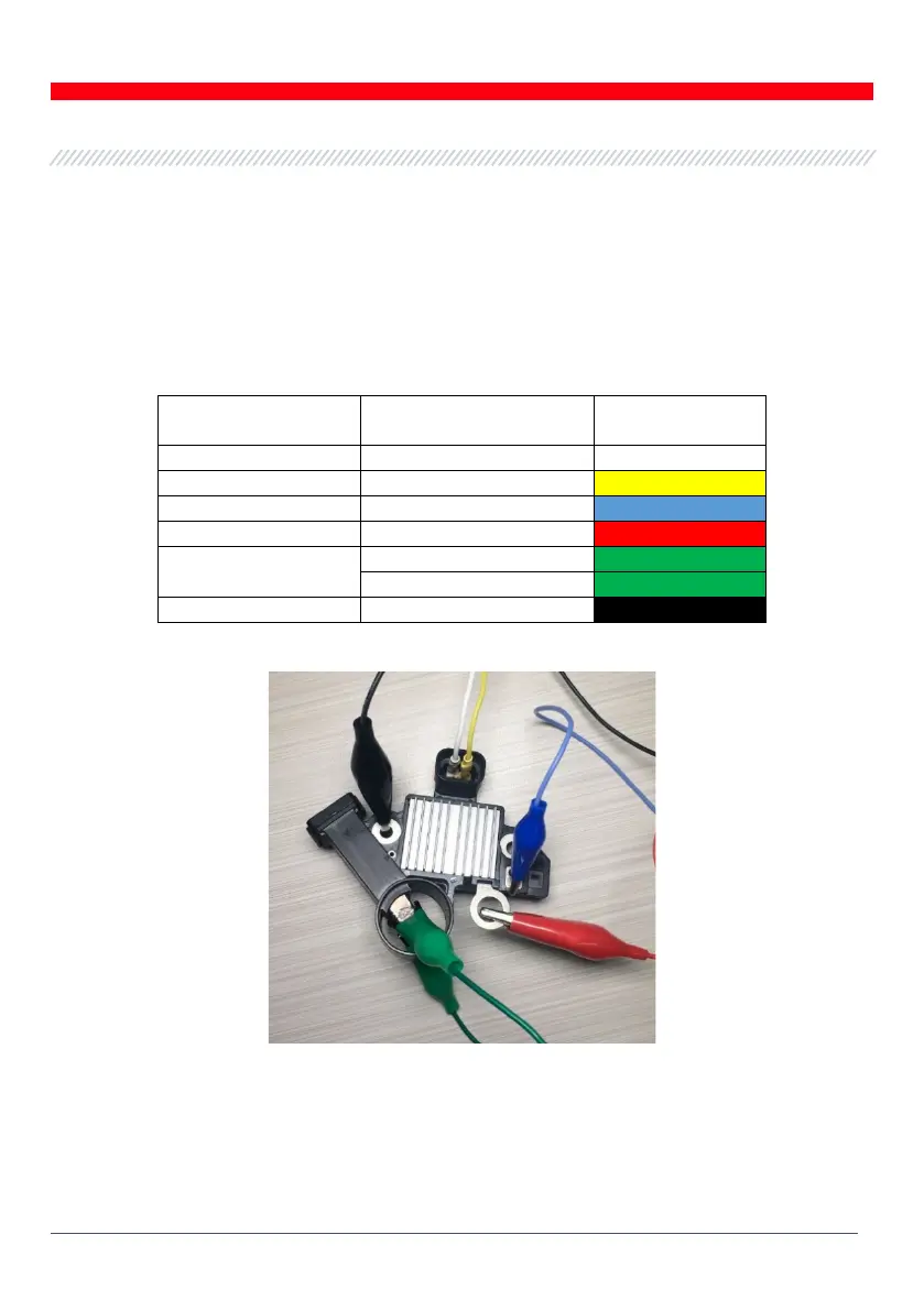
Table 2 – Connection of voltage regulator ARE1054 to the tester
Voltage regulator
terminal
Tester output terminal
DF
Figure 20 - Diagram of voltage regulator ARE1054 connection to the tester