EasyManuals Logo

MTD 700 Series Shop Manual

MTD 700 Series
150 pages
To Next Page IconTo Next Page
To Previous Page IconTo Previous Page
Page #119 background imageLoading...
Page #119 background image
Discharge Chute and Controls (Joystick, Hex Shaft)
115
NOTE: If working on a 2-way joystick, skip to step 11.
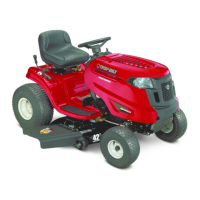
10. Remove the lock nut from the left side housing using
a 1/2” wrench. See Figure 10.28.
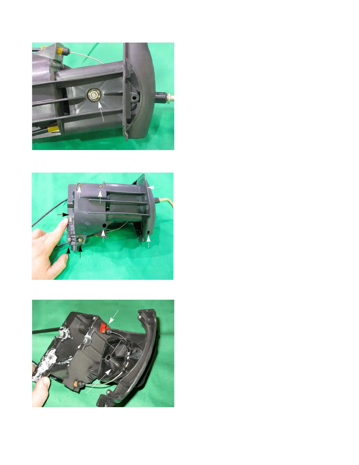
11. Remove the eight screws that holds the housing
assembly together using a #2 Phillips screwdriver.
See Figure 10.29.
12. Lift the right housing off of the left housing.
NOTE: If working on a 2-way joystick, skip to step 15.
13. Put an identifying mark on one of the Pitch Cables to
identify which cable goes to which hole. See Figure
10.30.
14. Remove the cables and the Cable Guide.
Figure 10.28
Lock nut
Figure 10.29
Figure 10.30
Identifying Mark
Cable Guide

Table of Contents

Other manuals for MTD 700 Series

Questions and Answers:

Question and Answer IconNeed help?

Do you have a question about the MTD 700 Series and is the answer not in the manual?

MTD 700 Series Specifications

General IconGeneral
Turning Radius18 inches
Engine TypeSingle-cylinder
Drive TypeRear-wheel drive
Tire Size (Front)15x6.00-6
Tire Size (Rear)20x10.00-8

Related product manuals