8.20.2 Engine Control Unit – Removal and installation
Preconditions
☑ Engine is stopped and starting disabled.
Special tools, Material, Spare parts
Designation / Use Part No. Qty.
Engine Control Unit
(→ Spare Parts Catalog) 1
Rubber mount
(→ Spare Parts Catalog)
NOTICE
Wrong engine governor installed.
Engine damage!
• When reassembling an engine, make sure that the governor with the data record for the given engine
is installed.
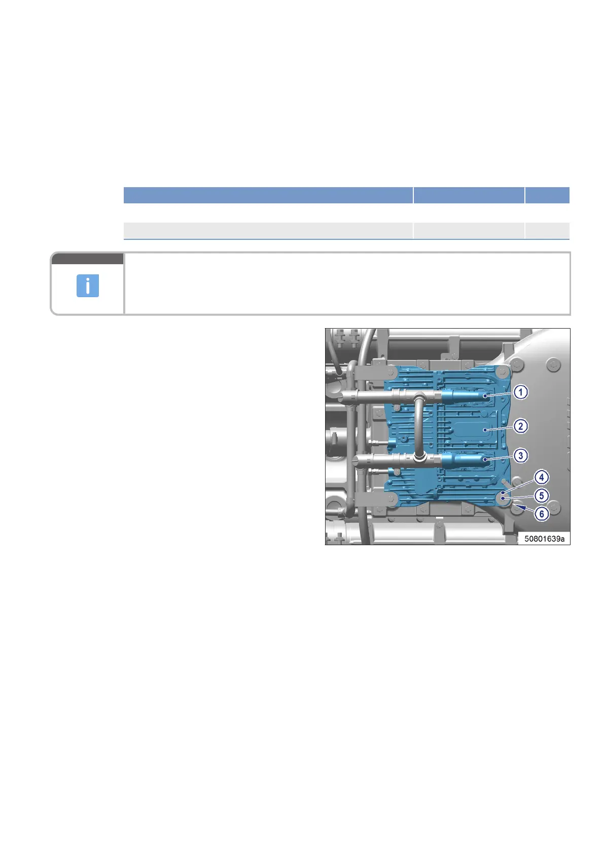
Removing Engine Control Unit
from engine
1. Note or mark assignment of cables and con-
nectors.
2. Undo latches on connectors (1), (2) (custom-
er connection) and (3).
3. Disconnect all connectors.
4. Remove all screws (5) with washers (4).
5. Take off Engine Control Unit.
Installing Engine Control Unit on engine
1. Install in reverse order. Ensure correct assignment of connectors and sockets.
2. Check damping element (6) prior to installation.
Result: Replace damping element (6) if porous or faulty.
MS15054/03E 2018-07 | Engine Governor | 219
TIM-ID: 0000053492 - 003
 Loading...