User Manual
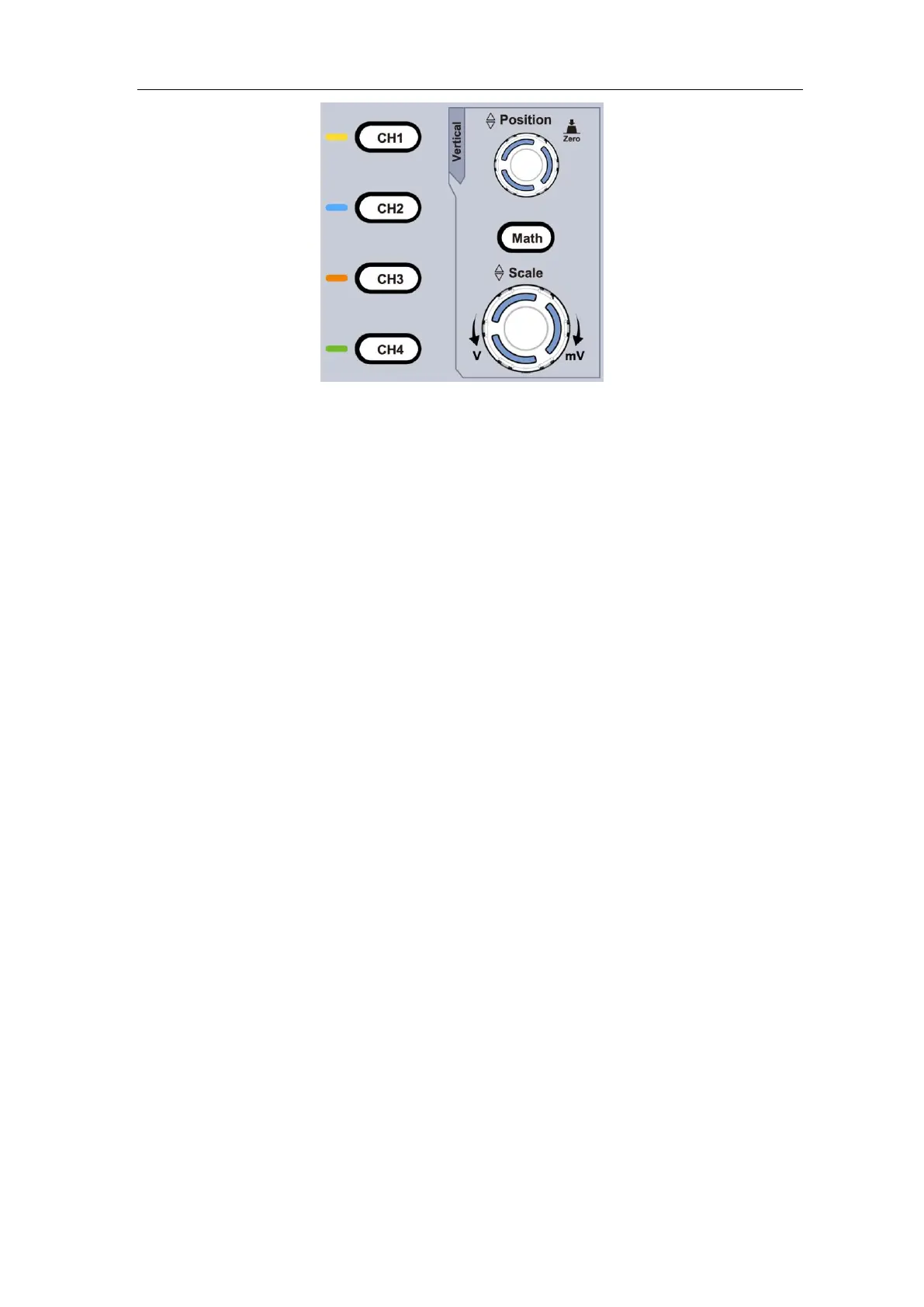
Figure 3-10 Vertical Control Zone
The following practices will gradually direct you to be familiar with the using of the
vertical setting.
1. Press CH1, CH2, CH3 or CH4 to select the desired channel.
2. Use the Vertical Position rotary control to show the selected channel waveform in
the center of the waveform window. The Vertical Position rotary control functions
the regulating of the vertical display position of the selected channel waveform. Thus,
when the Vertical Position rotary control is rotated, the pointer of the earth datum
point of the selected channel is directed to move up and down following the
waveform, and the position message at the center of the screen would change
accordingly.
Measuring Skill
If the channel is under the DC coupling mode, you can rapidly measure the DC
component of the signal through the observation of the difference between the wave
form and the signal ground.
If the channel is under the AC mode, the DC component would be filtered out. This
mode helps you display the AC component of the signal with a higher sensitivity.
Vertical offset back to 0 shortcut key
Turn the Vertical Position rotary control to change the vertical display position of the
selected channel, and push the position rotary control to set the vertical display
position back to 0 as a shortcut key, this is especially helpful when the trace position
is far out of the screen and want it to get back to the screen center immediately.
3. Change the Vertical Setting and Observe the Consequent State Information Change.
With the information displayed in the status bar at the bottom of the waveform
window, you can determine any changes in the channel vertical scale factor.
Turn the Vertical Scale rotary control and change the "Vertical Scale Factor (Voltage
Division)" of the selected channel, it can be found that the scale factor of the selected
channel in the status bar has been changed accordingly.