User Manual
common baud.
Custom Baud: adjust M rotary control to choose
baud, ranges from 50 to 10,000,000.
Data Bits:Set as 5、6、7、8 bits.
Data:Set data according to data bits, ranges from 0-31,
0-63, 0-127 or 0-255.
Acquire waveform even no trigger occurred
Acquire waveform when trigger occurred
When trigger occurs, acquire one waveform then stop
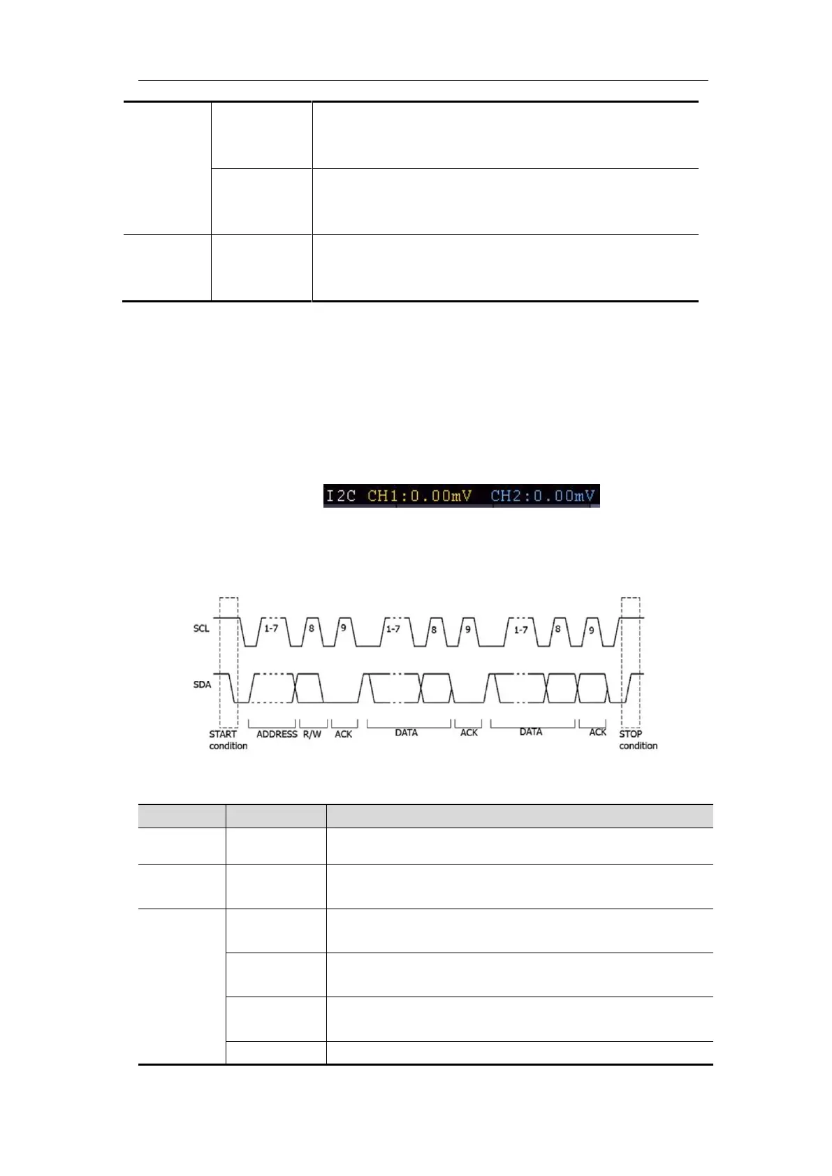
2. I2C Trigger
The I2C serial bus consists of SCL and SDA. The transmission rate is determined by
SCL, and the transmission data is determined by SDA. As shown in below figure,
oscilloscope can trigger on the start, restart, stop, ack lost, specific device address or
data value, also device address and data value at the same time.
In I2C bus trigger mode, the trigger setting information is displayed on bottom right
of the screen, for example, ,indicates that
trigger type is I2C, CH1 trigger level is 0.00mV, CH2 trigger level is 0.00mV.
I2C Trigger menu list:
Set vertical channel bus type as I2C trigger.
Trigger when SDA data transitions from high to low
while SCL is high.
When another start condition occurs before a stop
condition.
Trigger when SDA data transitions from low to high
while SCL is high.
Trigger when SDA data is high during any