14 Part Number 9294699 12/16/15
Installation Section 2
CONNECTIONS
See “System Pressures” on page 10 and “Regulator Settings &
Location” on page 11
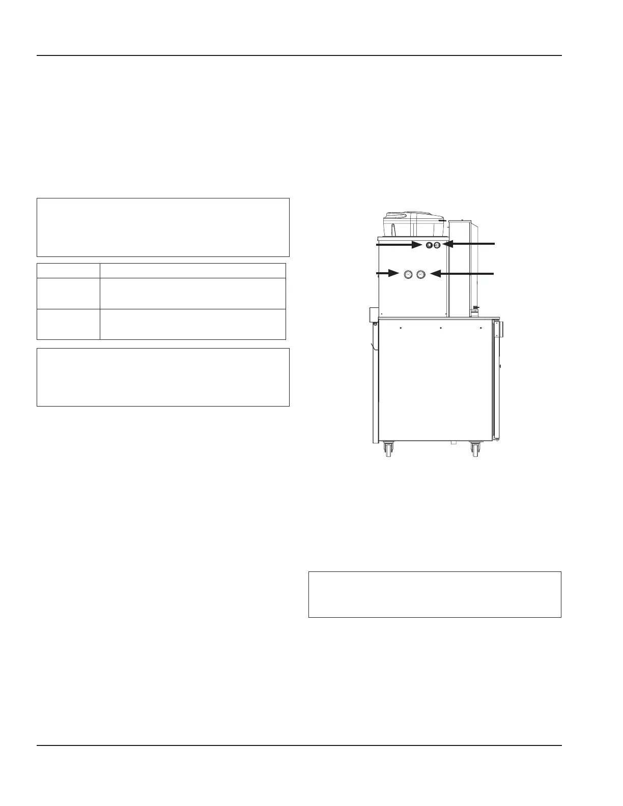
1. Confirm correct orientation of Water and Air/CO
2
fittings.
2. The line set included with the unit should be equipped
with male quick connect fitting(s) for the water supply
line(s) and female quick connect fitting(s) for the Air/
CO2 supply line
Important
Leave enough slack in the water/CO
2
/drain lines to allow
access to the rear of the machine without disconnecting
the lines.
REGULATOR SETTINGS (During Flowing Conditions)
Pumps
Air / CO
2
35 psi
(0.24 MPa, , 241 kPa, 2.41 bar)
Plain Water
35 psi
(0.24 MPa, 241 kPa, 2.41 bar)
Important
Regulators are factory set but will need to be checked
and possibly adjusted under flowing conditions once
the unit is operational.
See “How to Check Product Pumps Air/CO2 Pressure” on page
66 and “How to Check Plain Water Pressure” on page 67
3. Coil excess tubing and secure with tie straps.
Drain
See “Drain Connections” on page 11
4. Route drain line (minimum 1” ID) to drain, maintaining
a 2” (51 mm) air gap. Cut to proper length if needed (do
not leave loops in drain).
Electrical
See “Electrical” on page 12
5. If all electrical and grounding requirements have been
followed proceed to insert electrical plug from BIC into
wall receptacle.
6. Turn power switch on the left hand side of the unit to
the ON position.
Air/CO2 (Pumps)
Regulator
35 psi (0.24 MPa,
241 kPa, 2.41 bar)
Plain Water
Regulator
35 psi (0.24 MPa,
241 kPa, 2.41 bar)
ON/OFF
Switch
USB Port
7. The touch screen should energize and inform the user to
perform Zone 2 & 3 cleaning before the unit can be put
into operation. See “Start-up & Cleaning” on page 15
Important
Do not add product to the machine until cleaning and
sanitizing are complete.
 Loading...