RX1575 SERIES TRENCH ROLLER • OPERATION MANUAL S/N 3069933~ — REV. #0 (11/29/23) — PAGE 41
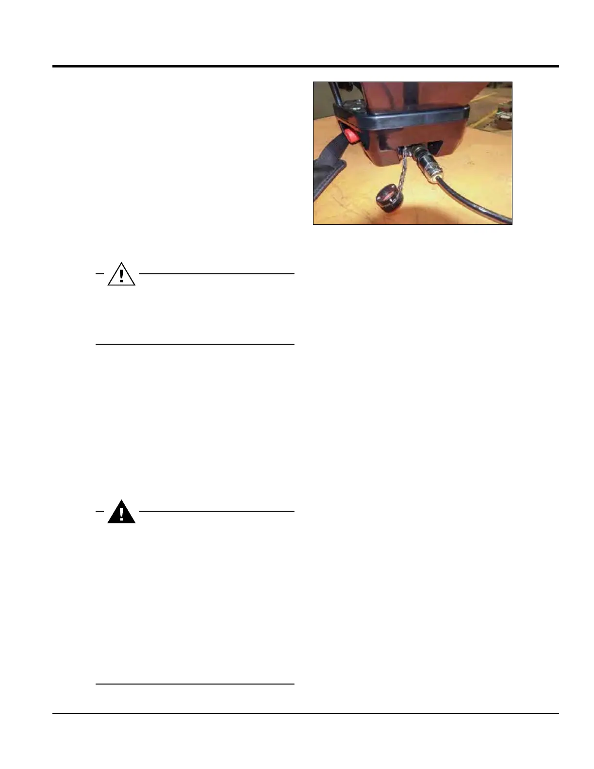
INFRARED REMOTE CONTROL UNIT CABLE CONNECTION
2.6 Actuators and dashboard instruments
2.6.2.2 Cable connection
• Cable connection is used to physically connect the remote
control and the machine. Once the remote control is con-
nected, all commands and communications are carriedpout
out via the cable. The protected zone is active. Keep visibility
between the remote control and the sensor.
• The cable connection is functional even if the battery is re-
moved from the remote control.
• Charging of the remote control is indicated by an indicator
lamp when the remote control is connected to the machine
via cable. It is possible to operate the machine while the re-
mote control is charging using the cable.
• Charging the remote control is possible even if the engine
is switched o.
• Turn the key in the ignition box to the “I” position.
Charging of the remote control with the engine swit-
ched o is limited to 2 hours only to avoid draining the
machine battery. After 2 hours, charging is automatically
interrupted.
Automatic pairing function
• If you wish to control the machine via the remote control,
you must rst perform a mutual assignment of addresses.
This is only necessary when registering a new remote con-
trol to the machine.
• Connect the cable to the remote control.
• Turn the ignition key to the “I” position.
• Activate the remote control by moving the engine start le-
ver to the “I” position.
• After about 3 seconds, you can disconnect the cable.
If more than one machine is operated in parallel at the
site, check that the machine is correctly paired with the
remote control before starting the engine.
Switch the key of machines within possible range to the
“I” position. Then activate the warning horn (5) – ma-
chines must be in standby mode 2 and within range of
the control signal. The machine that responds to the
warning horn command is paired with the controller.
If more than one machine responds to this command,
re-pair the remote controls to the appropriate machines
and repeat the test.
If the above procedure is still not successful, contact ser-
vice. Only one machine can continue working, the other
must be secured against use.