Manual MVK-MP
V 3.5 19
3.2.9 Connection of Digital Sensors and Actuators
Pin 2
Function channel 1x
Parameterizable channel or input or
output
Pin 4
Function channel 0x
Parameterizable channel or input or
output
Fig. 9: Configuration of the M12 port
Modules with sockets that are only output (55274 socket 0-3 and 55290 socket 0-7)
do not supply +24 Volt on Pin 1. Pin 2 and Pin 4 are digital outputs that cannot be
parameterized as input.
Unused sockets have to be fitted with blind caps in order to ensure IP67
protection.
3.2.10 Sensor Supply
Sensors can be supplied via pin 1 (+24 V) and pin 3 (0 V) of the M12 sockets. The sensor supply of
each M12 socket is secured. This fuse automatically resets under 100mA. If the current is > 100mA, a
reset has to be done via the sensor supply. The max. current draw for the sensor supply is 200 mA for
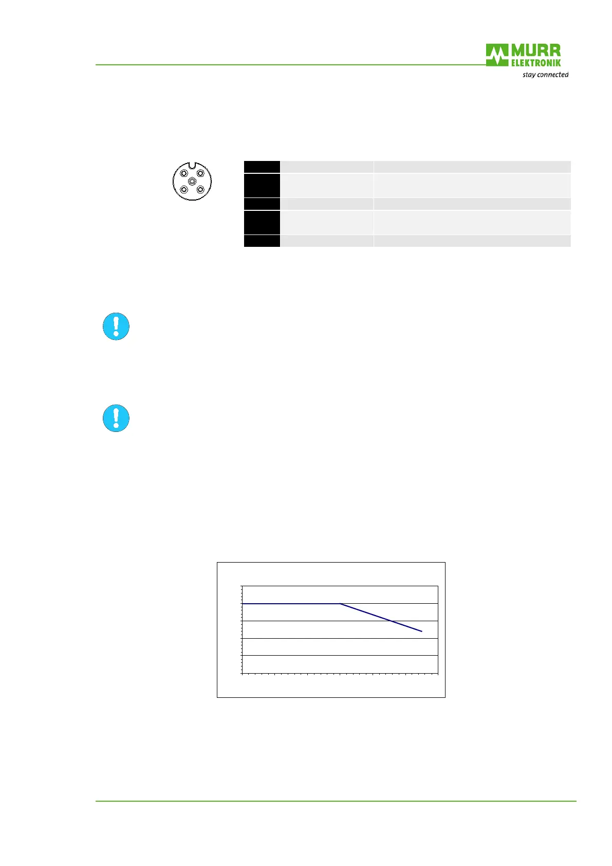
each M12 socket. Please see the following derating diagram:
Derating Sensorversorgung
0
50
100
150
200
250
0 10 20 30 40 50 60
Fig. 10: Derating Sensor Supply
We recommend observing a cable diameter of min. 0.34mm² in order to ensure fast switching off in
case of short-circuit.

 Loading...


