EasyManuals Logo

Murr Elektronik MVK-MP User Manual

Murr Elektronik MVK-MP
74 pages
To Next Page IconTo Next Page
To Previous Page IconTo Previous Page
Page #22 background imageLoading...
Page #22 background image
Manual MVK-MP
22 V 3.5
B
B
3.2.15 Connection of Analog Sensors
The sensor supply is identical to the supply of digital modules.
Pin 1
+ 24 V / 0,2 A
Sensor supply
Pin 2
A+
Signal input
Pin 3
0 V
Reference potential
Pin 4
0 V
Reference potential
Pin 5
FE
Fig. 14: M12 Socket Assignment
Unused sockets have to be fitted with blind caps in order to ensure IP67
protection.
3.2.16 Using Analog Sensors 0 to 10 V
Sensors with signal 0 to 10 V can be directly connected to the analog voltage
input.
Fig. 15: Using Analog Sensors 0 to 10 V
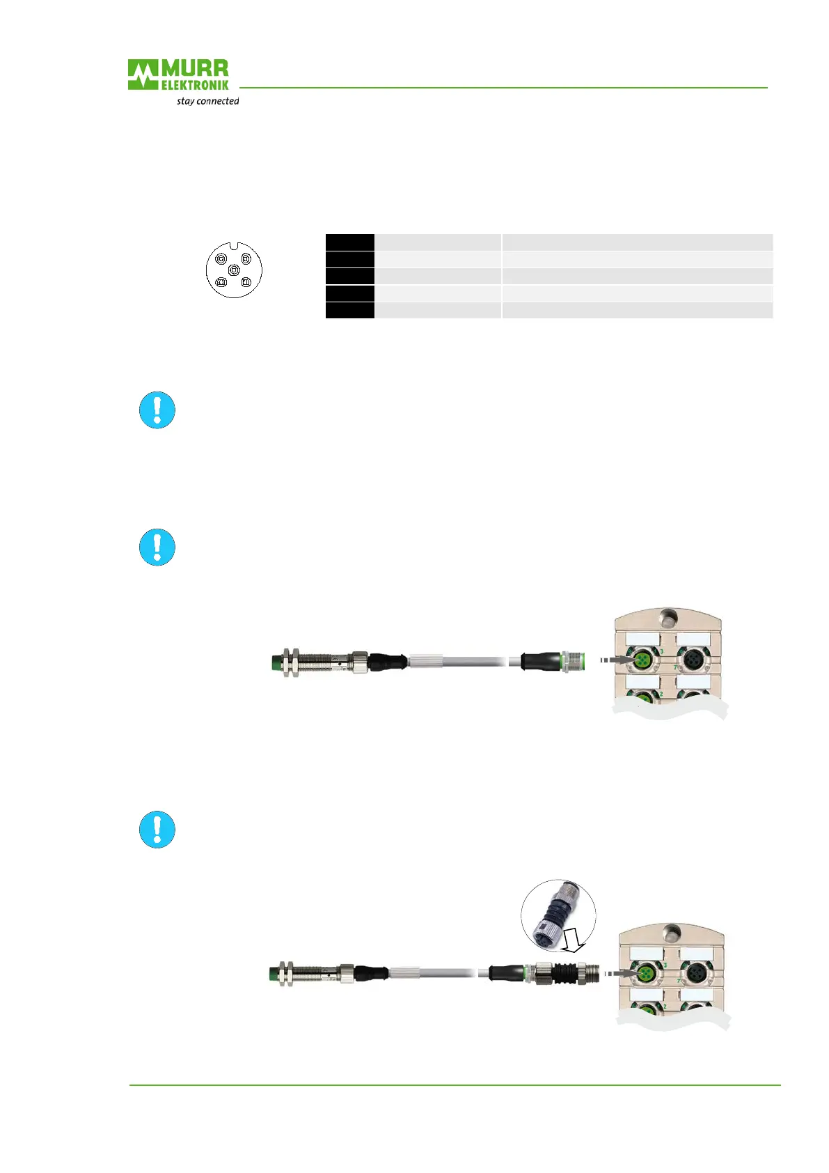
3.2.17 Using Analog Sensors 0 to 20 mA or 4 to 20 mA
Sensors with signals 0 to 20 mA or 4 to 20 mA have to be connected to the analog
voltage input via an M12 adapter (on the module) (Art.-No. 7000-42251-0000000).
Fig. 16: Using Analog Sensors 0 to 20 mA or 4 to 20 mA
3
2
5
1
4

Table of Contents

Questions and Answers:

Question and Answer IconNeed help?

Do you have a question about the Murr Elektronik MVK-MP and is the answer not in the manual?

Murr Elektronik MVK-MP Specifications

General IconGeneral
BrandMurr Elektronik
ModelMVK-MP
CategoryControl Unit
LanguageEnglish

Related product manuals