Manual MVK-MP
V 3.5 21
3.2.13 Connection of Sensors/Actuators with Diagnostic Output
When sensors or actuators with diagnostic output are used (e.g. accoring to Desina standard), you can
also evaluate this diagnostic signal, and process and represent it in the controller or visualization unit
using a conventional I/O system.
In this case there will be no visual error display close to the defective sensor, which might also be
installed in a place not visible. The visual signal at the M12 socket of the MVK-MP facilitates thus on-
site troubleshooting.
This helps to detect:
Front surface damage
defective electronics and
wire break.
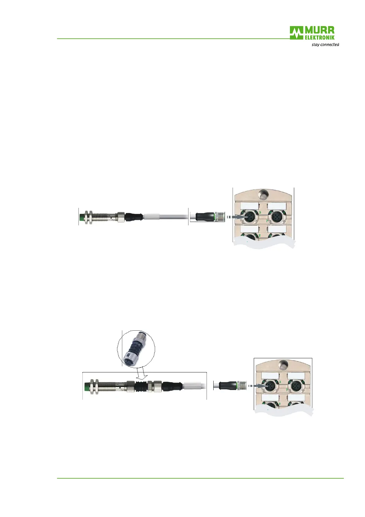
Fig. 12: Connection of Sensors/Actuators with Diagnostic Output
3.2.14 Cable Break Monitoring
With the M12 diagnostic adapter; Murrelektronik offers a simple tool for monitoring the M12 cables to
the sensors and actuators regarding cable breaks on the wires 1 and 2, in case you do not use Desina
sensors or actuators.
Fig. 13: Cable Break Monitoring

 Loading...


