Manual MVK-MP
V 3.5 43
5. Diagnostic
5.1 LED General Information
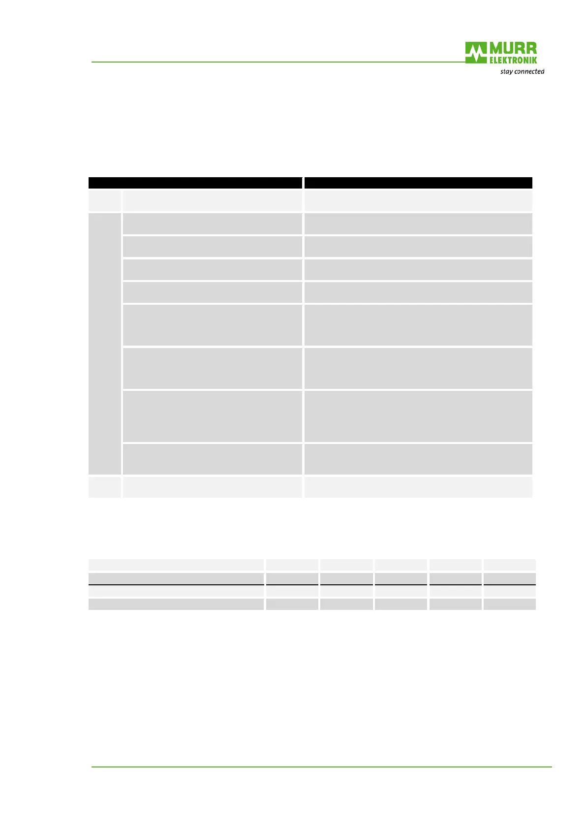
Signification for Bus Run LED
green
Profibus - DP data exchange -
flashing
green
No DP data exchange
Possible cause
Segment without supply. Supply segment.
No address or invalid address set. Set correct address.
The address set is already used.
Every Profibus segment must have an explicit and
unique address
Terminating resistor between master and
segment is switched on.
When the terminal resistor of a Profibus plug is switched
on, the following segment is usually separated from the
Profibus. Check whether only the terminal resistors at
the end of the Profibus segment are switched on.
Wrong termination of the Profibus segment
Both ends of a Profibus segment must be fitted with a
terminal resistor. With low baud rates the network can
apparently be operated despite wrong termination. This
may cause sporadic faults during operation.
Stub Lines
Baud rates up to 1.5 Mbit/s max. 6.6m
With higher baud rates, stub lines are not
admissible.
If stub lines cannot be avoided, preferably use specific
“active” stub lines or repeaters. Please note that the
number of repeaters used in a segment is limited.
Please refer to the relevant documentation of the
Extension of the Profibus segment is too
large.
For addmissible cable lengths see table.
Use repeaters for dividing large segments into several
segments.
Off
Profibus firmware not yet initialized Initializing the bus node may take some seconds
Tab. 19: LED General Information
Tab. 20: Baud rates
5.2 LED Display
Channel-related diagnostics are displayed at the M12 socket via the LED assigned to this particular
channel. Four LEDs, located beside the BUS LED, display the state of the supply voltage. The following
tables show the relationship between cause of error and LED display. Please note the difference
between MVK-MP with parameterizable outputs and the MVK-MP DI8 (DI8) with no outputs and the
MVK-MP DO8 (DO8) with no inputs.

 Loading...


