3.1 Field bus I/O signals
3-1
Chapter 3 Signal allocation
3.1 Field bus I/O signals
The I/O signals of the field bus differ depending on whether PLC is enabled or disabled. In addition, the I/O
points to which signals are assigned is determined based on the field bus channel number to be used.
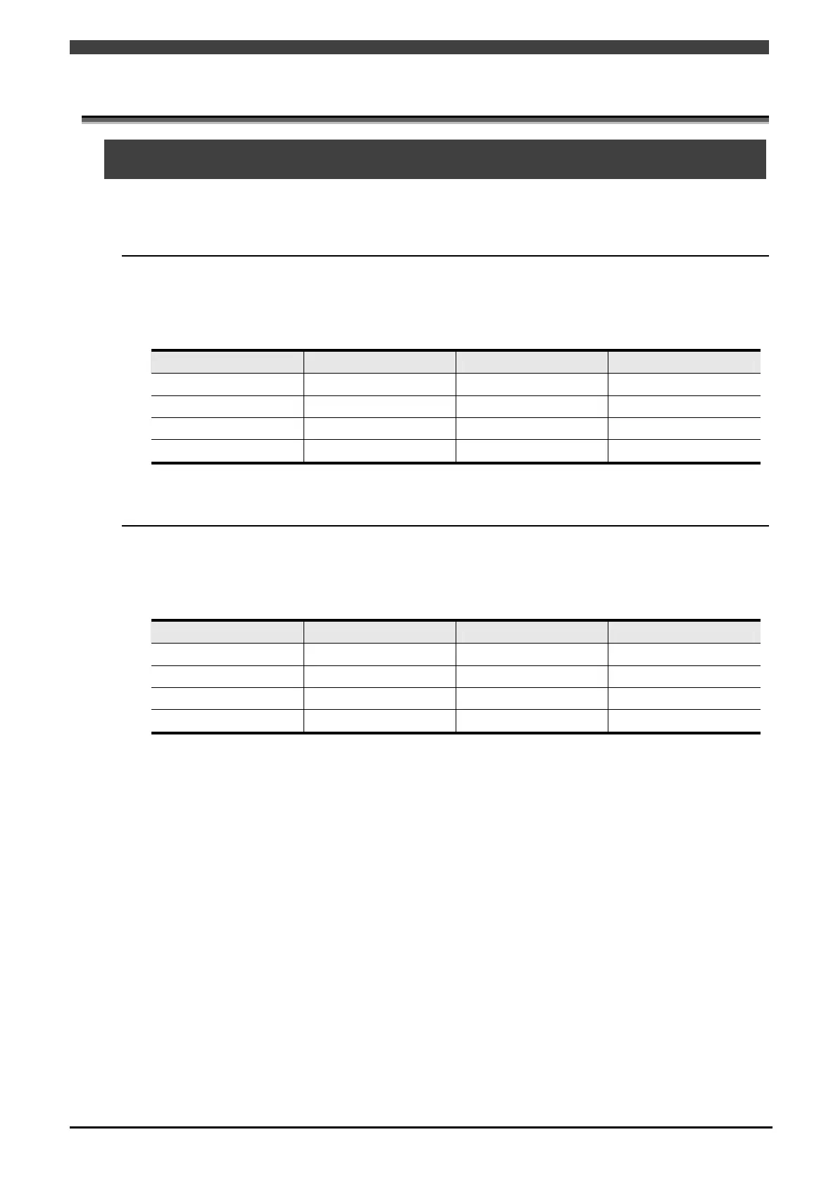
3.1.1 When software PLC is enabled
When software PLC is enabled, signals are assigned to field bus relay inputs (X1000 ~ X3047) and outputs
(Y1000 ~ Y3047).
Table 3.1.1 I/O assignments when software PLC is enabled
Channel number Input Output Number of points
Channel 1 X1000 ~ X1511 Y1000 ~ Y1511 512 pts (64 bytes)
Channel 2 X1512 ~ X2023 Y1512 ~ Y2023 512 pts (64 bytes)
Channel 3 X2024 ~ X2535 Y2024 ~ Y2535 512 pts (64 bytes)
Channel 4 X2536 ~ X3047 Y2536 ~ Y3047 512 pts (64 bytes)
Total: 2,048 pts
3.1.2 When software PLC is disabled
When software PLC is disabled, signals are assigned to the inputs (I161 ~ I2048) and outputs (O161 ~
O2048) of general-purpose I/O.
Table 3.1.2 I/O assignments when software PLC is disabled
Channel number Input Output Number of points
Channel 1
I161 ~ I672 O161 ~ O672
512 pts (64 bytes)
Channel 2
I673 ~ I1184 O673 ~ O1184
512 pts (64 bytes)
Channel 3
I1185 ~ I1696 O1185 ~ O1696
512 pts (64 bytes)
Channel 4
I1697 ~ I2048 O1697 ~ O2048
352 pts (44 bytes)
Total: 1,888 pts