3.1 Field bus I/O signals
3-2
3.1.3 Assigning signals beyond the number of channels
The field bus can use up to four channels. If all four channels are not being used, it is possible to use the
signal assignment region of channels not being used.
The description below gives an example in which software PLC is enabled. Signals can be assigned using a
similar concept even if software PLC is disabled.
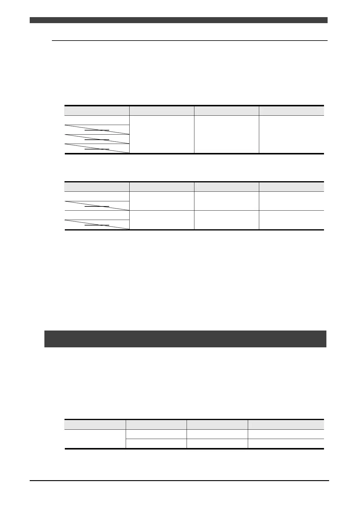
If only one channel is being used, all 2048 points can be used with just “Channel 1” by using “Channel 1”.
Table 3.1.3 I/O assignment when using only one channel
Channel number Input Output Number of points
Channel 1
Channel 2
Channel 3
Channel 4
X1000 ~ X3047 Y1000 ~ Y3047
2,048 pts (256 bytes)
When using two channels, 1024 points can be used for each channel, by using “Channel 1” and “Channel 3”.
Table 3.1.4 I/O assignment when using only two channels
Channel number Input Output Number of points
Channel 1
Channel 2
X1000 ~ X2023 Y1000 ~ Y2023
1,024 pts (128 bytes)
Channel 3
Channel 4
X2024 ~ X3047 Y2024 ~ Y3047
1,024 pts (128 bytes)
3.2 EtherNet/IP signal assignment
The assignment of signals is determined based on the channel numbers of the field bus being used.
If EtherNet/IP is used in this controller, I/O is simply assigned beginning from the signal position determined
based on the channels being used. If the number of I/O bytes is smaller than the number of signals assigned to
each channel, an unused assignment region results.
The description below gives an example in which the system is set to use “Channel 1” as the slave, with two
bytes of input and three bytes of output.
Table 3.2.1 Example of slave signal assignment
Channel number Input Output Remark
X1000 ~ X1015 Y1000 ~ Y1023
Usable assignment region
Channel 1
X1016 ~ X1511 Y1024 ~ Y1511
Unused assignment region