4.2 EtherNet/IP slave settings
4-4
4.2.2 EtherNet/IP (slave) settings
Channel settings
1
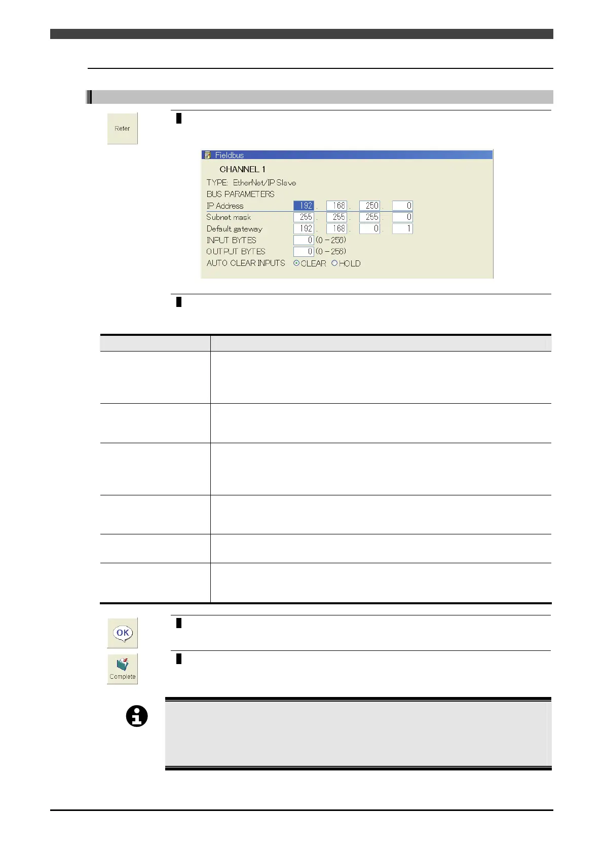
On the [3 Fieldbus] setting screen, align the cursor with the channel for which
EtherNet/IP (slave) is selected, and press the f key <Refer>.
>> The following screen will appear.
2
Set each parameter.
Table 4.2.1 Parameter of [3 Fieldbus] setting screen (at the EtherNet/IP slave settings)
Parameter Description of function
IP Address
Input the IP address for the corresponding node.
It is used to identify the device on the network. Devices having the same node
number cannot be set on the same network.
The last number of the IP address must be other than “0”.
Subnet mask
Input the subnet mask for the corresponding node.
It is used to manage the network by splitting it into sub-networks. Set the same
value for all devices on the same network.
Default gateway
Input the default gateway for the corresponding node.
Sometimes this setting is not required in cases where there is no router on the
network.
Be sure to consult with your network administrator when making settings.
INPUT BYTES
Input the input bytes from the field bus base board.
It is the size of data input to this controller. Eight signals can be sent/received in
one byte.
OUTPUT BYTES
Input the output bytes to the field bus base board.
It is the size of data output from this controller.
AUTO CLEAR INPUTS
Select the input signal status when a communication error has occurred.
When the input signal statuses are to be cleared, “CLEAR” is selected. On the
other hand, when to be held, “HOLD” is selected.
3
Upon completion of the settings, press the f key <OK>.
>> The display returns to [3 Fieldbus] setting screen.
4
On the [3 Fieldbus] setting screen, press the f key <Complete>
>> The setting is saved to the internal memory.
IMPORTAN
Be sure to use PLCEngine/EDS_ABS_EIP_V_1_9.eds located in system memory for the EDS
file required to set this controller for scanners being used.
For details on how to set scanners, see the operating manual for your scanner hardware.
The newest EDS file can be downloaded from the website of HMS Industrial Networks.
http://www.anybus.com/