1.2 EtherNet/IP of this controller
1-2
1.2 EtherNet/IP of this controller
1.2.1 I/O signals
EtherNet/IP of this controller supports up to four independent networks (channels). Each of these channels
functions independently as a scanner or an adapter.
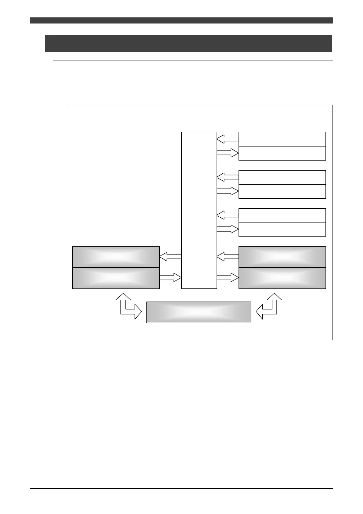
The diagram below gives an operational block diagram of the EtherNet/IP.
Physical I/O Software PLC Logical I/O
Network I/O
Fieldbus output
(Y1000 ~ Y3047)
Logcal output
(O0000 ~ O2047)
Standard output
Standard input
Fixed output
Fixed input
Extended output
Extended input
Fieldbus input
(X1000 ~ X3047)
Logical input
(I0000 ~ I2047)
Fig. 1.2.1 Operational block diagram
Two methods of accessing network I/O from this controller are available.
When using PLC, access is carried out using field bus I/O having 2048 input points (X1000 to X3047) and 2048
output points (Y1000 to Y3047).
When not using PLC, access is carried out using logical I/O having 1888 input points (I161 to I2048) and 1888
output points (O161 to O2048).