4.1 Setting procedure
4-2
INFO.
・In EtherNet/IP, the device called a “slave” on DeviceNet is called an “adapter”.
("EtherNet/IP slave" in this controller means "EtherNet/IP adapter".)
・In EtherNet/IP, the device called a “master” on DeviceNet is called an “scanner”.
("EtherNet/IP master" in this controller means "EtherNet/IP scanner".)
Setting example
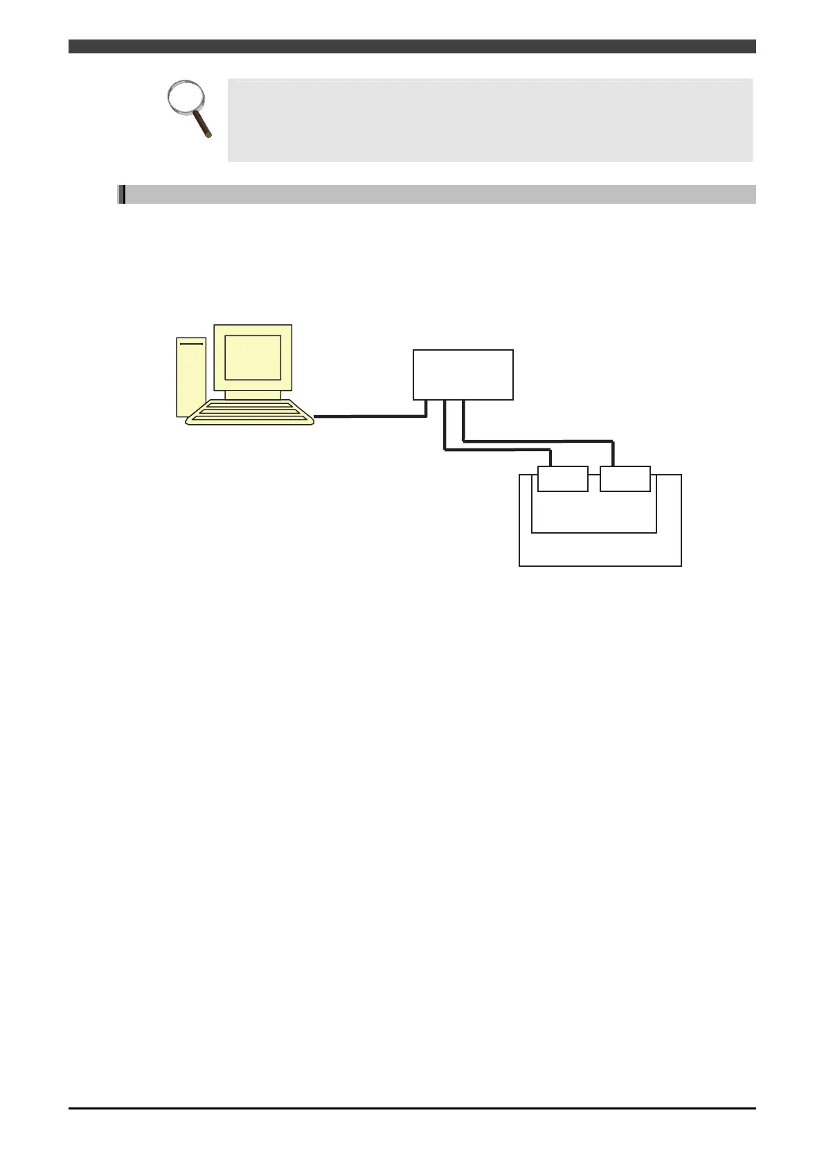
The following figure shows the setting example of the configuration used in this chapter.
・Configuration of Robot controller
Set master as module1 of base board. Set slave as module2 of base board.
Connect them to setting PC via a hub.
Fig. 4.1.2 Configuration example
・Setting of field bus
CH1 AnyBusEtherNet/IP Mater module 1
CH2 No use
CH3 AnyBusEtherNet/IP Slave module 2
CH4 No use
・Master detailed settings (CH1)
IP address and so on are omitted.
Input byte number 128
Output byte number 128
・Slave detailed settings (CH3)
IP address and so on are omitted.
Input byte number 128
Output byte number 128
・PC settings
The IP address of the PC must belong to the identical network with the robot controller.
Setting PC
HUB
Base board
Master Slave
Robot controller
172.18.233.71
172.18.233.59
172.18.233.60
RSLinx Classic
RSNetWorx for EtherNet/IP