FPΣ
8.2 Connection Example with External Device
8-13
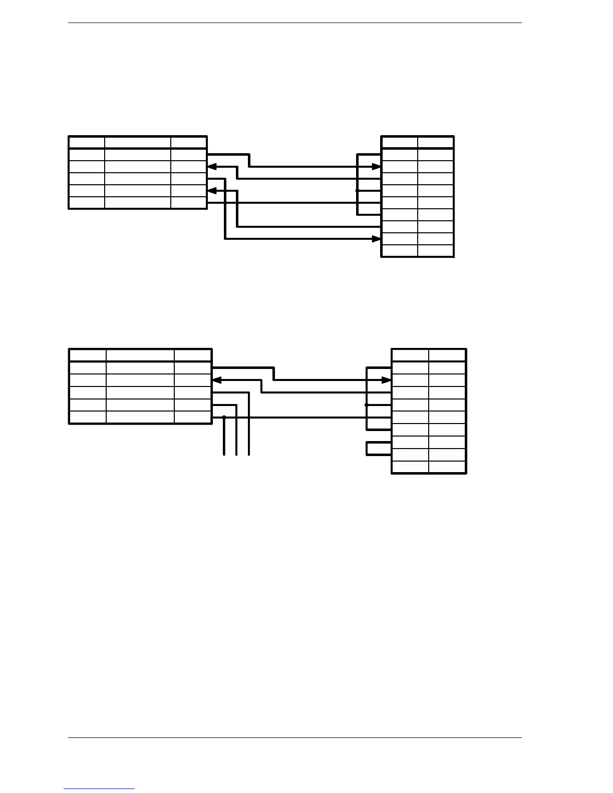
Connection example with computer
When using the 1-channel RS232C type of communication cassette
FPΣ side (5-pin)
Pin name Signal name Abbre.
SD
RD
RS
CS
SG
Transmitted Data
Received Data
Request to Send
Clear to Send
Signal Ground
SD
RD
RS
CS
SG
Computer side
(D-SUB 9-pin)
Symbol
CD
RD
SD
ER
SG
DR
RS
CS
RI
Pin No.
1
2
3
4
5
6
7
8
9
Figure 149: FPΣ Computer link - connection example 1 (computer)
When using the 2-channel RS232C type of communication cassette
FPΣ side (5-pin)
Pin name Signal name Abbre.
S1
R1
S2
R2
SG
Transmitted Data 1
Received Data 1
Transmitted Data 2
Received Data 2
Signal Ground
SD
RD
SD
RD
SG
Computer side
(D-SUB 9-pin)
Symbol
CD
RD
SD
ER
SG
DR
RS
CS
RI
Pin No.
1
2
3
4
5
6
7
8
9
(To other device)
Figure 150: FPΣ Computer link - connection example 2 (computer)
Programming for a computer link
Touse a computer link, a program should be created that enables command messages
to be sent and response messages to be received on the computer side. The PLC
automatically sends back a response to commands. No communication program is
required on the PLC side.
Also, if a software program such as PCWAY is used on the computer side, PLC data
can be easily compiled, without having to think about the MEWTOCOL-COM.

 Loading...

