FPΣ
Communication Function 1 Computer Link
8-16
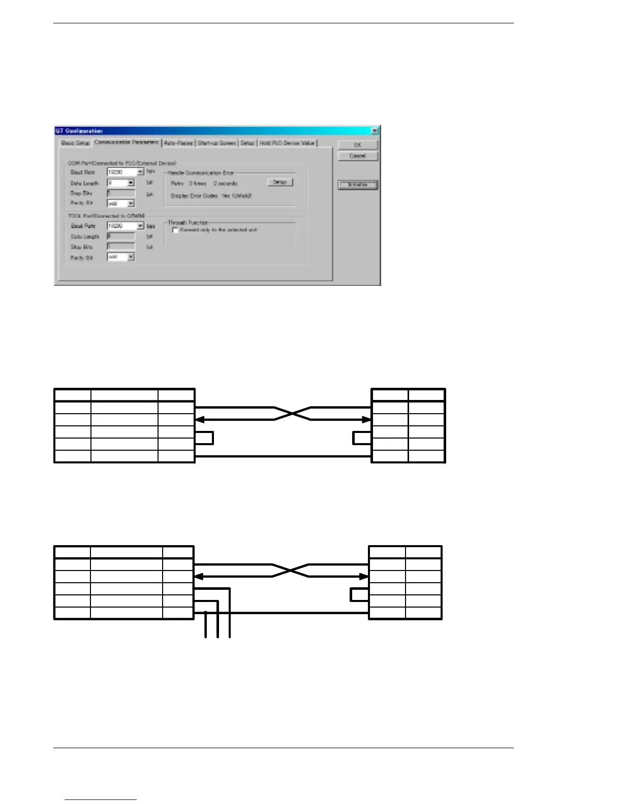
Communication condition settings are specified using the parameter settings for the
programmable display and the “GT Configuration” item in the GTWIN screen creation
tool. For detailed information, please see the technical manual for the GT10/GT30.
GTWIN GT Configuration settings “Communication Parameters” screen
Figure 152: GTWIN GT Configuration setting screen (communication prameters)
Connection example with programmable display “GT10/GT30”
When using the 1-channel RS232C type of communication cassette
FPΣ side (5-pin)
Pin name Signal name Abbre.
SD
RD
RS
CS
SG
Transmitted Data
Received Data
Request to Send
Clear to Send
Signal Ground
SD
RD
RS
CS
SG
GT10/GT30 side (5-pin)
Symbol
SD
RD
RS
CS
SG
Pin No.
1
2
3
4
5
Figure 153: FPΣ Computer link - connection example 1 (GT10)
When using the 2-channel RS232C type of communication cassette
FPΣ side (5-pin)
Pin name Signal name Abbre.
S1
R1
S2
R2
SG
Transmitted Data 1
Received Data 1
Transmitted Data 2
Received Data 2
Signal Ground
SD
RD
SD
RD
SG
GT10/GT30 side (5-pin)
Symbol
SD
RD
RS
CS
SG
Pin No.
1
2
3
4
5
(To other device)
Figure 154: FPΣ Computer link - connection example 2 (GT10)

 Loading...

