FPΣ
8.2 Connection Example with External Device
8-17
Basic communication area setting for GT10/GT30
Tocarry outcommunication with a PLC,the “Basic Communication Area” setting for the
internal device area in the PLC reserved by the programmable display in advance
should be specified in the configuration settings.
When the GT10/GT30 is shipped from the factory, the basic communication area for
GT10/GT30 is set as shown below. “GT Configuration” settings should be changed to
match the application at hand.
Item Description
Word area DT0 to DT2
Bit area WR0 to WR2
The basic communication area is changed using the configuration parameter settings
for the programmable display and the “GT Configuration” item in the GTWIN screen
creation tool.
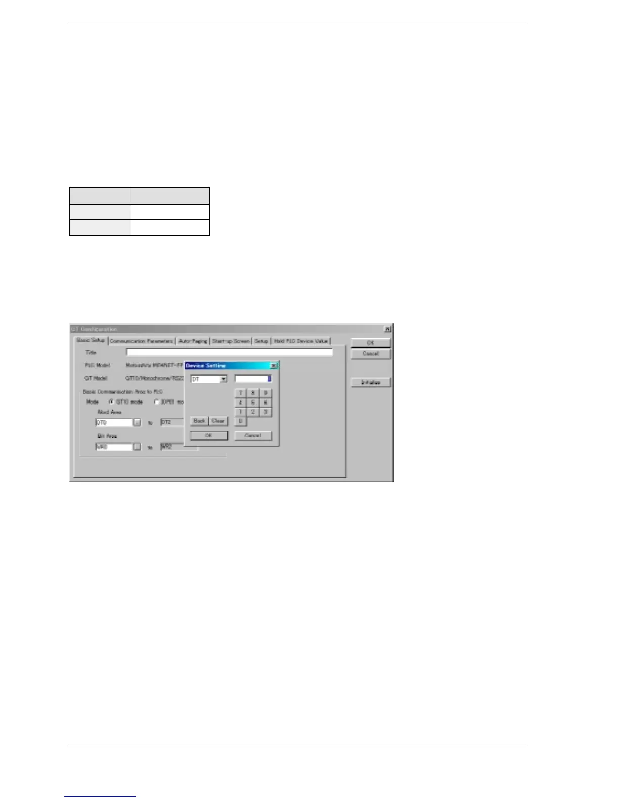
GTWIN GT Configuration settings “Basic Setup” screen
Figure 155: GTWIN GT Configuration setting screen (basic setup)

 Loading...

