FPΣ
Communication Function 2 General-purpose Serial Communication
9-26
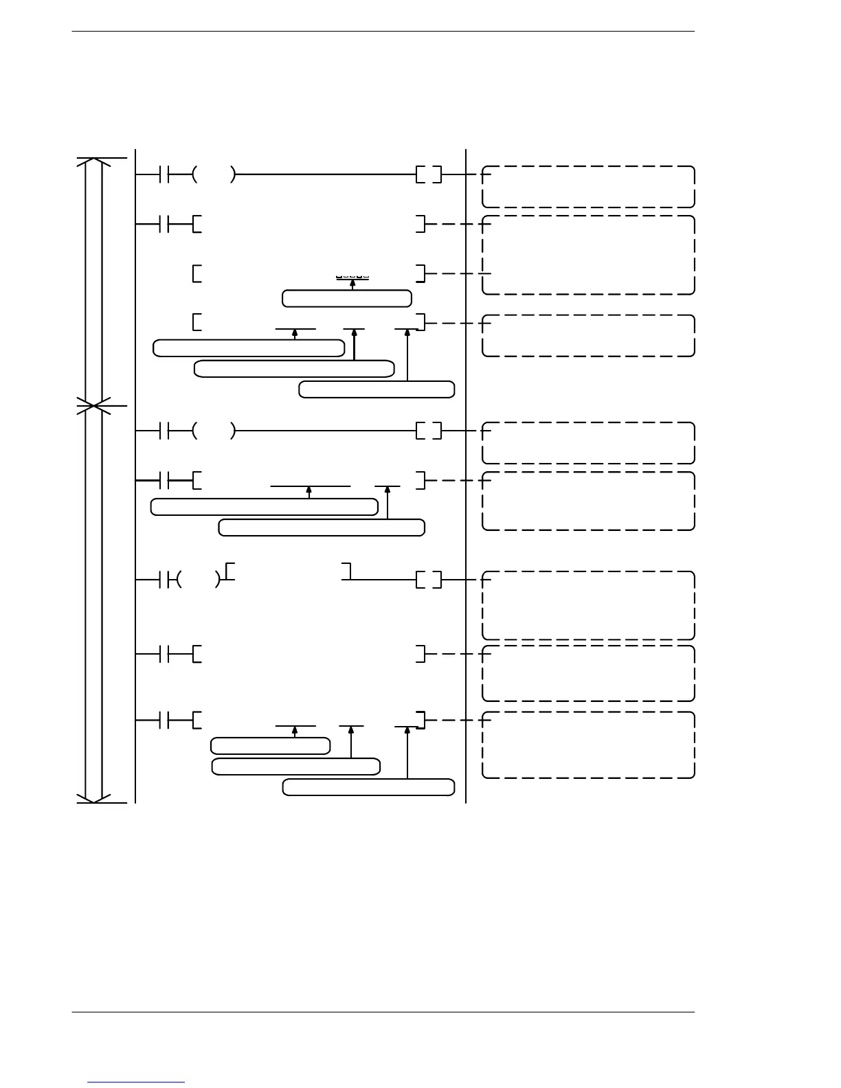
Sample program
The following shows an example in which an FP series PLC is connected to the COM.
1 port.
R0
DF
R10
R10
F159 MTRN
, DT 100
, K19 , K1
R9038
DF
, D201 , DT208 , DT0
R11
F10 BKMV
R11
R11
, DT 100 , K0 , K1F159 MTRN
M 00001** , DT107
F95 ASC ,
M %01#RDD00000, DT101F95 ASC ,
R11
=, DT1, H2431
DF
R12
, DT3 , DT50F72 AHEX , K8
R12
TransmissionReception
Data transmission command
The internal relay “R10” is turned on at the
timing of the transmission condition “R0”.
Data conversion
“%01#RDD00000” is converted to ASCII
code, and written to DT101 to DT106.
“00001**” is converted to ASCII code, and
written to DT107 to DT112.
Data transmission
The data in the transmission buffer is sent
from the COM. 1 port
Reception done detection
The internal relay “R11” is turned on at the
reception done contact “R9038” timing.
Retrieving received data
The received data in the received buffer is
read from the area in which it is stored
(DT201 to ) and sent to DT0.
Preparing to receive the next data
To prepare to receive the next data, the
F159 instruction resets the buffer writing
point and turns off the reception done con-
tact “R9038”, based on the empty data.
Five spaces inserted
Check of received data
To determine whether the received data is
a normal response, the comparison in-
struction is used to check whether the
character string “1$” is stored in DT1.
Check of received data
The eight-character ASCII code beginning
with DT3 is converted to a hexadecimal
value and stored in DT50 and DT51.
With DT100 as the transmission buffer
the contents consisting of 19 bytes of it
are sent from COM. 1 (K1) port.
Starting from DT100
the contents consisting of 0 bytes
are sent from the COM. 1 (K1) port.
The contents of 8 words from DT201 to DT208
are written to data registers DT0 to DT7.
Figure 191: FPΣ Sample program (for FP series PLC)

 Loading...

