FPΣ
9.3 Connection Example with External Devices
9-25
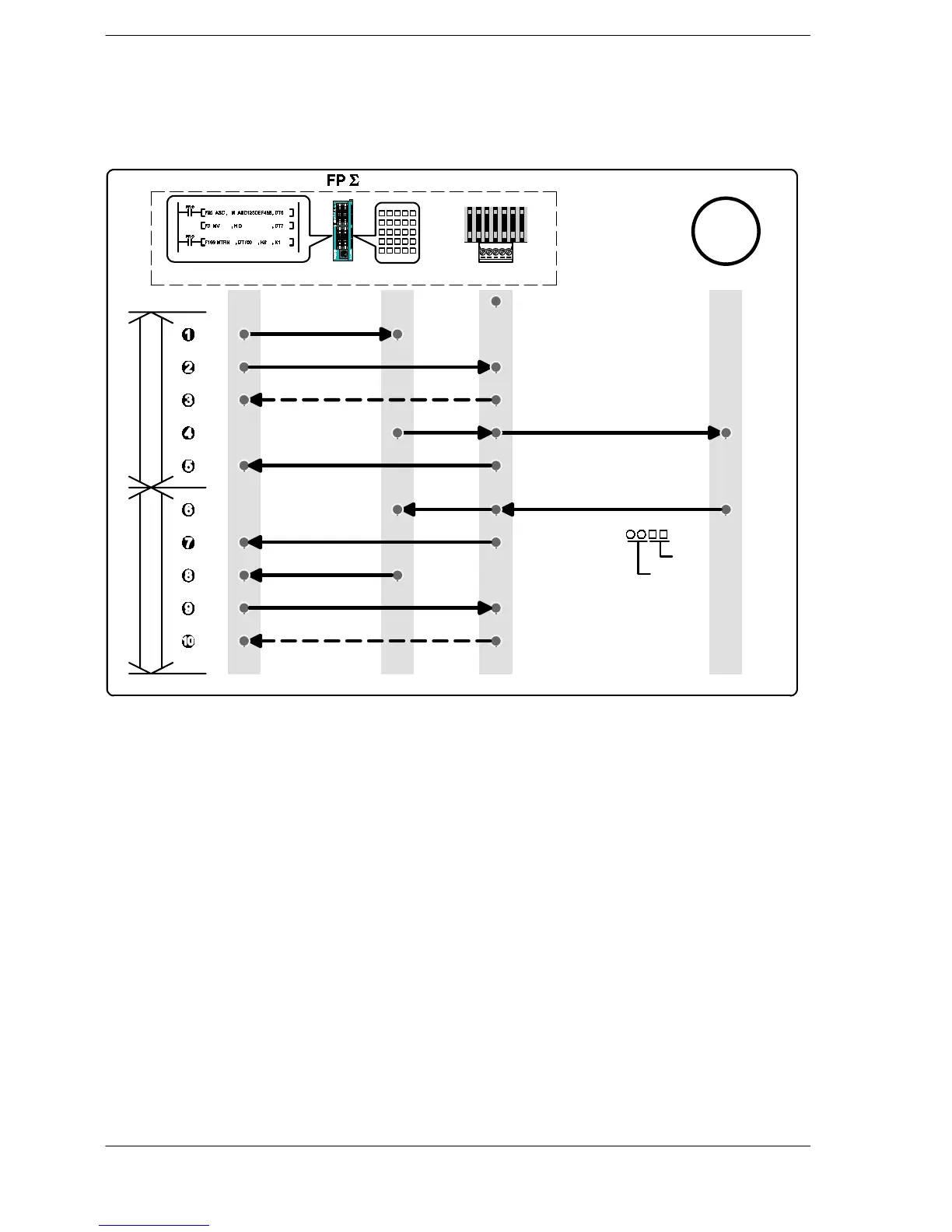
Procedure of communication
In this example, an FP series PLC is connected to the COM. 1 port, and “K100” is being
stored to DT0 of the PLC on the other end, and “K200” to DT1.
Ladder program
Transmission
Data transmission with F159 (MTRN)
Data register value of PLC on other end is received
“%01#RDD00000 00001 **
C
R
” transmission
Reception buffer writing point reset
Data register RS232C port
FP series PLC
Reception
R9039: off and R9038: off
Transmission done flag (R9039: on)
Reception done flag (R9038: on)
Empty data transmission with F159 (MTRN)
R9039: off and R9038: off
Reception buffer writing point reset
Data read
Data area read command is
set in transmission buffer
Data area reading command
Error code
If normal: “%01$RD6400C8006F
C
R
”
If error occurs: “%01!
C
R
”
BCC
Figure 190: FPΣ Procedure of communication (FP series PLC)

 Loading...

