FPΣ
Communication Function 2 General-purpose Serial Communication
9-24
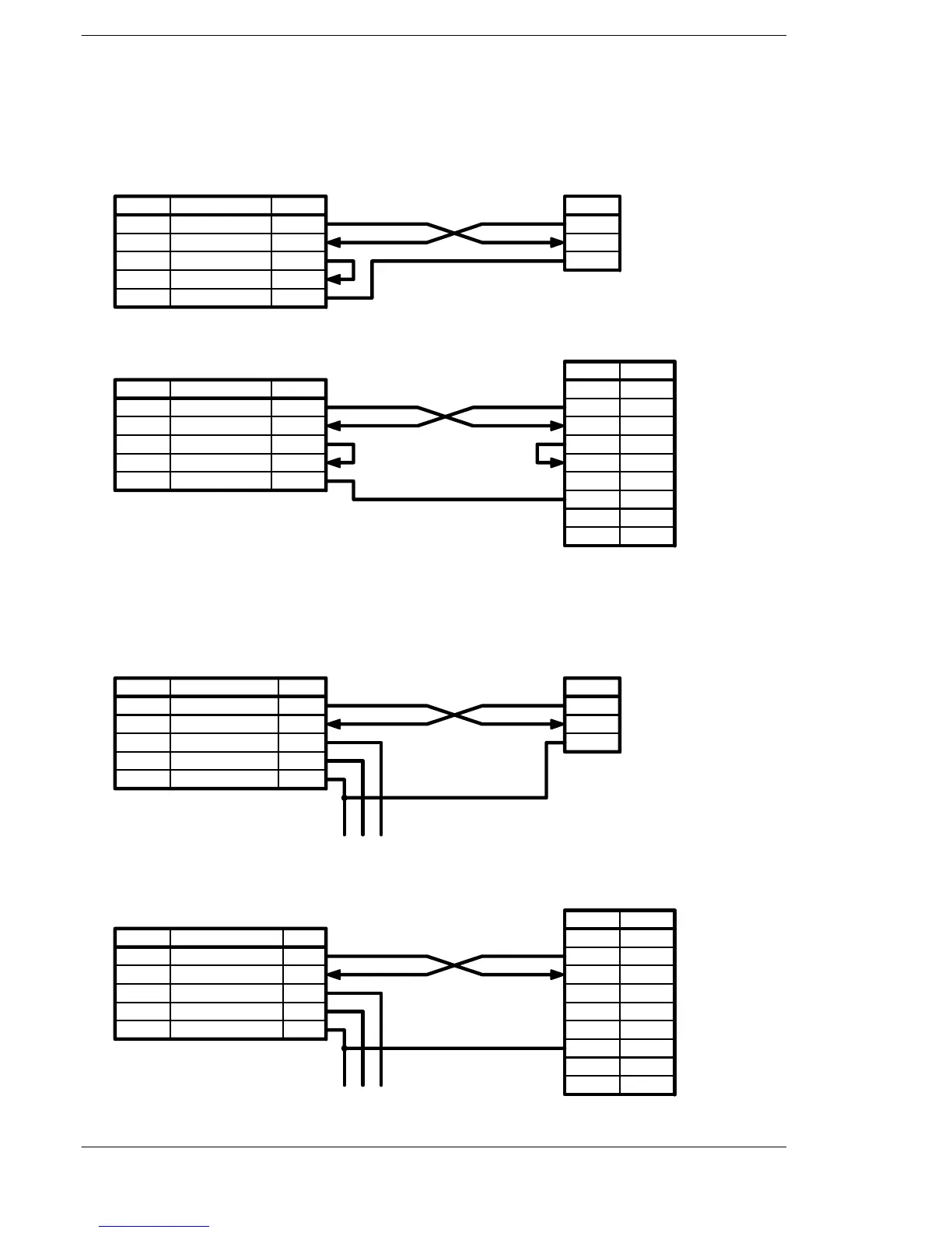
Connection example with FP series PLC (FP0, FP1)
• When using the 1-channel RS232C type of communication cassette
FPΣ side (5-pin)
Signal name Abbr.
SD
RD
RS
CS
SG
Transmitted Data
Received Data
Request to Send
Clear to Send
Signal Ground
SD
RD
RS
CS
SG
Pin name
FP0 COM. port
side (3-pin)
Symbol
S
R
G
Connection with FP0 COM. port
FPΣ side (5-pin)
Signal name Abbr.
SD
RD
RS
CS
SG
Transmitted Data
Received Data
Request to Send
Clear to Send
Signal Ground
SD
RD
RS
CS
SG
FP1 COM. port
side (9-pin)
Symbol
FG
SD
RD
RS
CS
—
SG
Pin No.
1
2
3
4
5
6
7
8
9
Pin name
—
—
Connection with FP1 COM. port
Figure 188: FPΣ Connection example with FP series PLC-1
• When using the 2-channel RS232C type of communication cassette
FPΣ side (5-pin)
Signal name Abbr.
S1
R1
S2
R2
SG
Signal Ground
SD
RD
SD
RD
SG
Pin name
FP0 COM. port
side (3-pin)
Symbol
S
R
G
Connection with FP0 COM. port
(To other device)
Transmitted Data 1
Received Data 1
Transmitted Data 2
Received Data 2
FPΣ side (5-pin)
Symbol
FG
SD
RD
RS
CS
SG
Pin No.
1
2
3
4
5
6
7
8
9
(To other device)
FP1 COM. port
side (9-pin)
Pin name Signal name Abbr.
S1
R1
S2
R2
SG
Transmitted Data 1
Received Data 1
Transmitted Data 2
Received Data 2
Signal Ground
SD
RD
SD
RD
SG
—
—
—
Connection with FP1 COM. port
Figure 189: FPΣ Connection example with FP series PLC-2

 Loading...

