FPΣ
Communication Function 3 PLC Link Function
10 - 14
Precautions when allocating link areas
If a mistake is made when allocating a link area, be aware that an error will result, and
communication will be disabled.
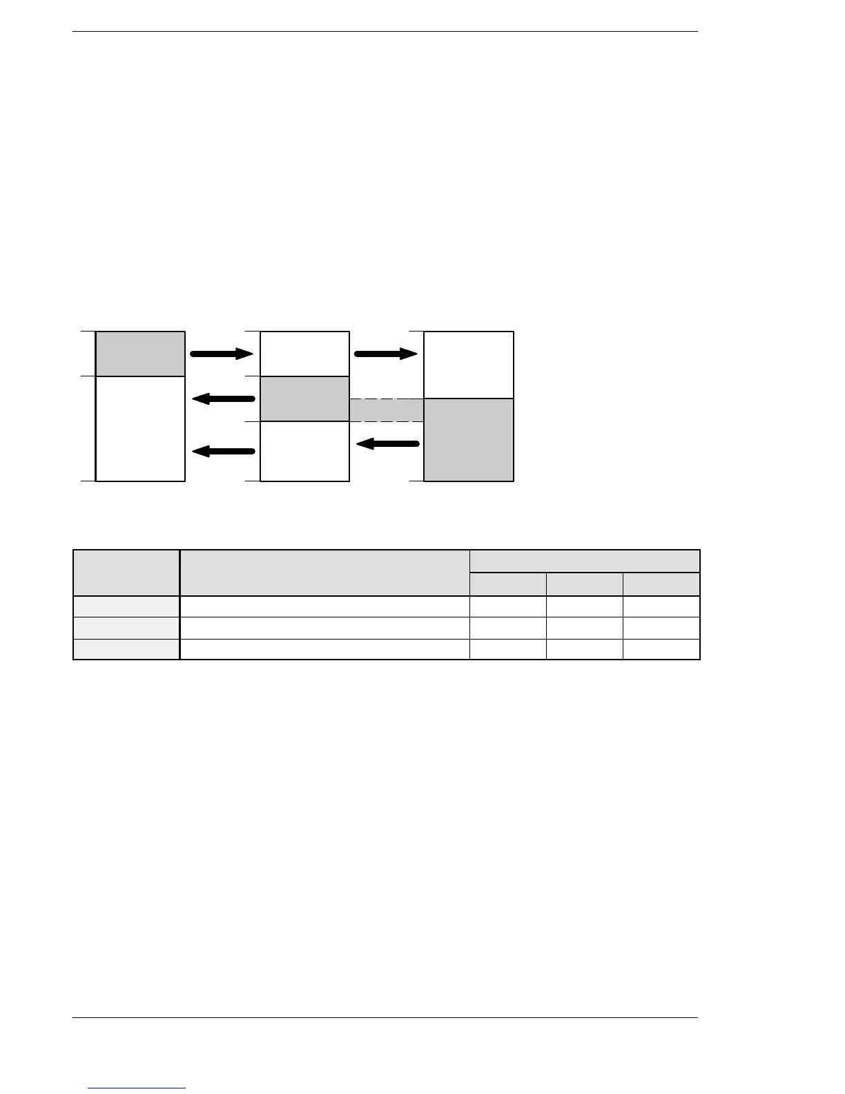
Avoid overlapping transmitted areas
Whensendingdatafrom thetransmittedarea tothe receivedareaofanotherFPΣ,there
must be a link relay and link register with the same number in the received area on the
receiving side. In the example shown below, there is an area between No. 2 and No.
3 which is overlapped, and this will cause an error, so that communication cannot be
carried out.
Link relay allocation
No.1
No.3
No.2
WL0
19
20
63
WL0
19
20
63
WL0
63
39
40
39
40
No.1
No.3
Transmitted
area
FPΣ
(Unit No. 1)
Receivedarea
Transmitted
area
FPΣ
(Unit No. 2)
Receivedarea
Receivedarea
Receivedarea
Transmitted
area
FPΣ
(Unit No. 3)
Overlap
Figure 213: Precautions when allocating link relay area
System register
No. Name Set value of various control unit
No. 1 No. 2 No. 3
No. 40 Range of link relay used for PLC link 64 64 64
No. 42 Starting no. for link relay transmission 0 20 30
No. 43 Link relay transmission size 20 20 34

 Loading...

