FPΣ
Specifications and Functions of Control Unit
2-4
1
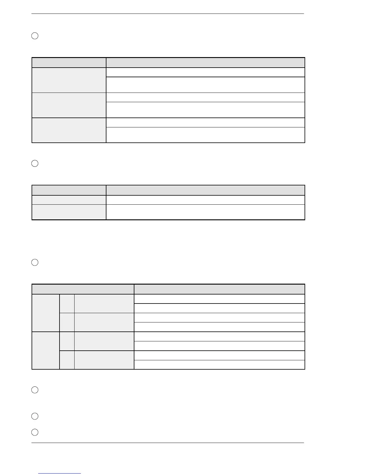
Status indicator LEDs
These LEDs display the current mode of operation or the occurrence of an error.
LED LED and operation status
RUN (green) Lights when in the RUN mode and indicates that the program is being executed.
It flashes during forced input/output.
(The RUN and PROG LEDs flash alternately.)
PROG. (green) Lights when in the PROG. mode and indicates that operation has stopped.
It flashes during forced input/output.
(The RUN and PROG LEDs flash alternately.)
ERROR/ALARM (red) Flashes when an error is detected during the self-diagnostic function.
Lights if a hardware error occurs, or if operation slows because of the program, and
the watchdog timer is activated.
2
RUN/PROG. mode switch
This switch is used to change the operation mode of the PLC.
Switch position Operation mode
RUN (upward) This sets the RUN mode. The program is executed and operation begins.
PROG. (downward) This sets the PROG. mode. The operation stops. In this mode, programming can be
done using tools.
When performing remote switching from the programming tool, the position of the mode
switch and the actual mode of operation may differ. Verify the mode with the status indicator
LED. Otherwise, restart the FPΣ and change the mode of operation with the RUN/PROG.
mode switch.
3
Communication status LEDs
These display the communication status of the COM.1 and COM.2 ports.
LED LED and communication status
COM.1 S Transmitted data
Flashes while data is being received
monitor
Goes out when no data is being received
4
Tool port (RS232C)
This port is used to connect a programming tool.
5
Input connector (10 pins × 2)
6
Input indicator LEDs

 Loading...

