FPΣ
High-speed Counter and Pulse Output Functions
6-18
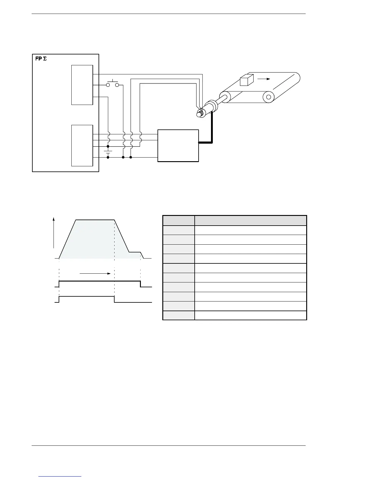
Positioning operations with a double speed inverter
Y0
Y1
+
-
X0
X5
COM
COM
Input terminal
Output terminal
Encoder
Motor
Operation/Stop
Inverter
Conveyor
Wiring example
Fast/Slow
Encoder input
Operation start
Inverter operation
Inverter
high-speed
Figure 81: FPΣ High-speed counter function - sample program 2 (wiring)
I/O No. Description
X0
Encoder input
X5
Operation start signal
Y0
Inverter operation signal
Y1
Inverter high-speed signal
R100
Positioning operation running
R101
Positioning operation start
R102
Arrival at deceleration point
R103
Positioning done pulse
R900C
Comparison instruction “<” flag
R903A
High-speed counter CH0 control flag
Figure 82: FPΣ High-speed counter function - sample program 2 (operation chart)
Y0
50004500
Y1
0
Speed
Number of pulse
Operation chart I/O allocation

 Loading...

