Wiring
FP0
7-9
Matsushita Automation Controls
7.4 Input Wiring
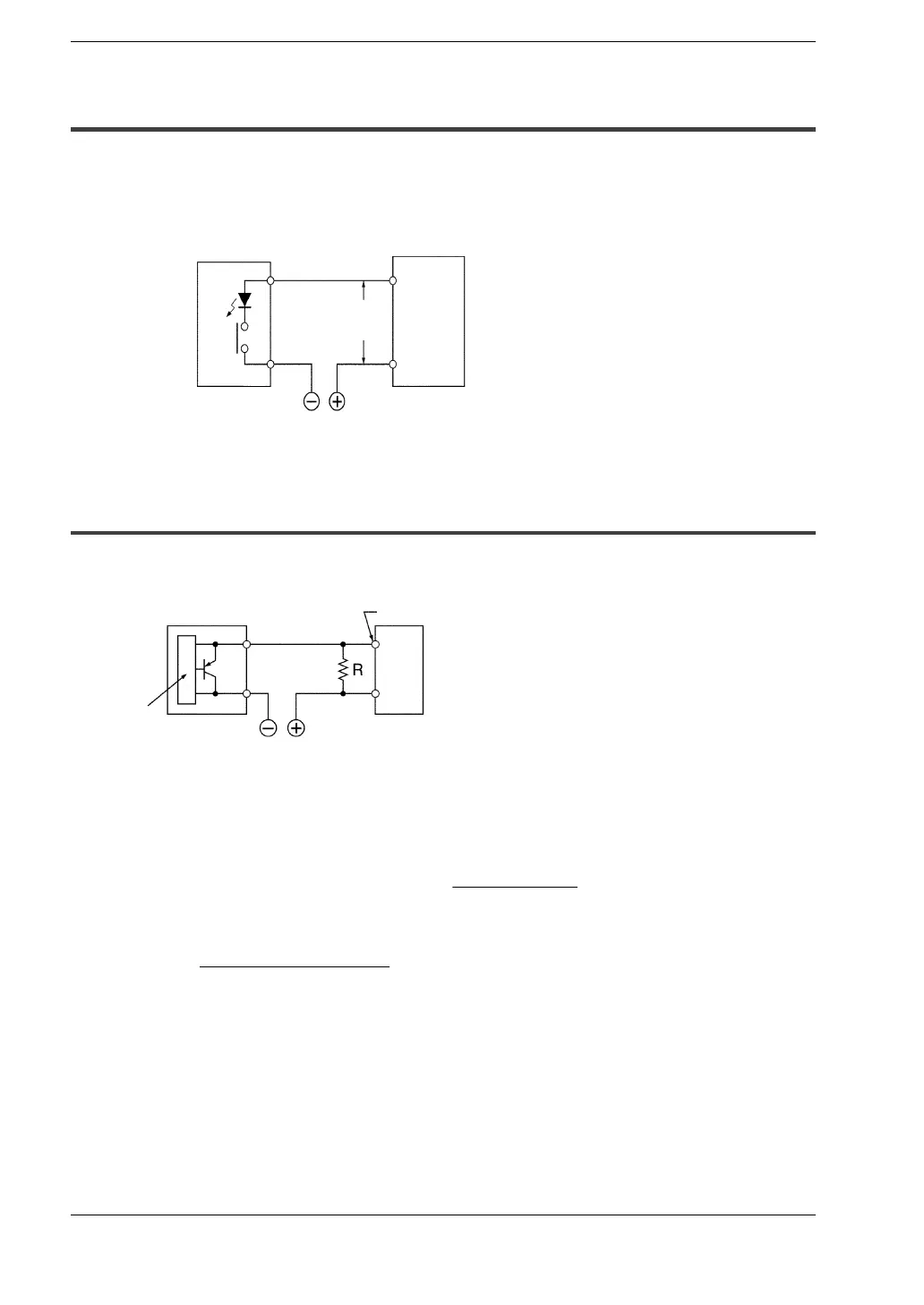
7.4.2 LED-Equipped Reed Switch
When a LED is connected to an input contact such as LED-equipped reed switch, make
sure that the ON voltage applied to the FP0 input circuit is greater than 19.2 V DC.
In particular, take care when connecting a number of switches in series.
FP0
19.2 V DC
or more
24 V DC
LED-equipped
reed switch
COM
Input
terminal
7.4.3 Two-Wire Type Sensor
If the input of the FP0 does not turn OFF because of leakage current from the two-wire
type sensor, the use of a bleeder resistor is recommended, as shown below.
The OFF voltage of the FP0 input is 2.4 V, therefore, select an R value so that the voltage
between the COM terminal and the input terminal will be less than 2.4 V.
(The impedance of the FP0 input terminal is 5.6 k
:
.)
The resistance R of the bleeder resistor is: R
≦
The wattage W of the resistor is:
In the actual selection, use a value that is 3 to 5 times the value of W.
13.44
(Power supply voltage)
2
R
(k
:
)
Two-wire
type sensor
FP0
5.6
×
I
2.4
W
=
COM
Input terminal
Internal
circuit
Bleeder
resistor
I
: Sensor’s leakage current (mA)
R: Bleeder resistor (k
Ω
)
 Loading...
