Wiring
FP0
7-11
Matsushita Automation Controls
7.5 Output Wiring
7.5 Output Wiring
.
Notes
D
There is no fuse protection built into the output circuit.
Therefore, in order to protect against overheating of the output
circuitry caused by possible short circuits, install an external
fuse at each point. However, in cases such as short circuits,
the control unit itself may not be protected.
D
Be sure to select the thickness (dia.) of the output wires while
taking into consideration the required current capacity.
D
Arrange the wiring so that the input and output wiring are
separated, and so that the output wiring is separated from the
power wiring, as much as possible. Do not route them through
the same duct or wrap them up together.
D
Separate the output wires from the power and high voltage
wires by at least 100 mm/3.937 in.
Protect the outputs as described below:
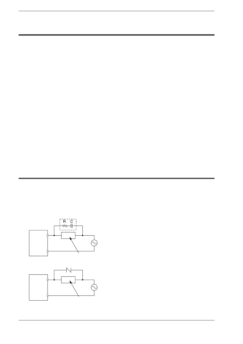
7.5.1 Protective Circuit for Inductive Loads
With an inductive load, a protective circuit should be installed in parallel with the load.
When switching DC inductive loads with FP0 relay output type, be sure to connect a
diode across the ends of the load.
When using an AC inductive load
Example of surge absorber:
[R: 50
Ω
, C: 0.47
μ
F]
AC inductive load
AC inductive load
Surge absorber (*)
(
*
)
COM
Output
terminal
COM
Output
terminal
Varistor
FP0
FP0
.
next page
 Loading...
