EasyManua.ls Logo

NAiS FP0-C32T User Manual

Default Icon
173 pages
To Next Page IconTo Next Page
To Previous Page IconTo Previous Page
Page #97 background imageLoading...
Page #97 background image
I/O AllocationFP0
5-3Matsushita Automation Controls
5.1 I/O Number
5.1 I/O Number
Expression of numbers for input/output relays
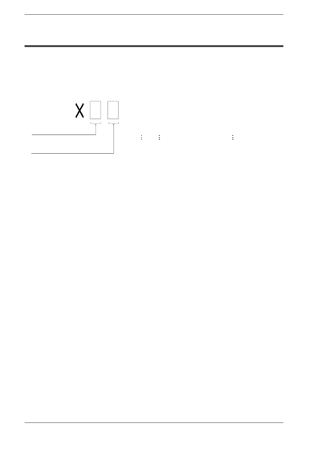
Since input relay (X) and output relay (Y) are handled in units of 16 points, they are
expressed as a combination of decimal and hexadecimal numbers as shown below.
Decimal
1,2,3 .....
Hexadecimal
0, 1, 2, 3 A,B F..... ...
X0, X1 XF...........................
X10, X11 X1F........................
X20, X21 X2F........................
<Example> External input relay (X)
Specifying X and Y numbers
On the FP0, the same numbers are used for input and output.
Example: The same number “X20 and Y20” can be used for input and output

Table of Contents

Questions and Answers:

NAiS FP0-C32T Specifications

General IconGeneral
ModelFP0-C32T
Output TypeTransistor
Total I/O Points32
Input Points16
Output Points16
Power Supply24V DC
Programming LanguageLadder Logic
Weight200 g
TypePLC
Data Memory3.2 kwords
Operating Temperature0 to 55°C
Storage Temperature-20 to 70°C
Humidity10% to 90% (non-condensing)

Summary

Chapter 1: FP0 Overview

FP0 Control Unit Components Overview

Details on the various components of the FP0 system, focusing on control units.

FP0 Expansion I/O Units Description

Description of various FP0 expansion I/O units.

FP0 Programming Tools Overview

Overview of software and hardware tools for FP0 programming.

Chapter 2: FP0 Control Units

FP0 Control Unit Parts and Terminology

Lists and describes the sixteen available types of FP0 control units.

FP0 Control Unit Type Illustrations

Diagrams illustrating different FP0 control unit models.

Control Unit Components and Connectors

Details on LEDs, switches, ports, connectors, and levers.

Tool Port Functionality and Pin Assignment

Details on the tool port and its pin assignment for programming.

General Specifications for FP0 Control Units

General specifications including voltage, current, temperature, and resistance.

Performance Specifications Overview

Details on program memory, instruction types, operation speed, and memory points.

Input Specifications Overview

Details on insulation, voltage, current, impedance, and points per common.

Relay Output Type Specifications

Specifications for relay output types, including capacity and life.

Transistor Output Type Specifications

Specifications for transistor output types, including voltage, current, and response.

Chapter 3: FP0 Expansion I/O Units

FP0 Expansion I/O Unit Type Illustrations

Illustrations of various FP0 expansion I/O unit models.

General Specifications for Expansion I/O Units

General specifications such as voltage, current, impedance, and temperature range.

Input Specifications for Expansion I/O Units

Input specifications including insulation, voltage, current, and points per common.

Relay Output Type Specifications (Expansion Units)

Specifications for relay output expansion units, including capacity and life.

Transistor Output Type Specifications (Expansion Units)

Specifications for transistor output expansion units, including voltage, current, and response.

Chapter 4: FP0 Analog I/O Unit

Analog I/O Unit Specifications Overview

Detailed technical specifications for analog I/O units.

Analog I/O Unit Wiring Guide

Instructions and diagrams for wiring analog I/O units.

Analog Mode Switch Settings Explained

Table detailing mode switch settings for various input/output ranges.

General Specifications for Analog I/O Unit

General specifications including voltage, current, impedance, and temperature range.

Analog Input Specifications Details

Details on input points, ranges, resolution, conversion speed, and precision.

Analog Output Specifications Details

Details on output points, ranges, resolution, conversion speed, and precision.

A/D Conversion Characteristics (Current Input)

A/D conversion tables and processing for current input ranges.

A/D Conversion Characteristics (Voltage Input)

A/D conversion tables and processing for voltage input ranges.

Analog Input Wiring Guide

Diagrams for wiring voltage, current, and thermocouple analog inputs.

Analog Output Wiring Guide

Diagrams for wiring analog voltage and current outputs.

Chapter 5: FP0 I/O Allocation

Chapter 6: FP0 Installation

Chapter 7: FP0 Wiring

Safety Instructions for Wiring

Safety precautions for wiring operations.

Wiring the Power Supply to the Control Unit

Procedure for connecting the power supply to the FP0 control unit.

Input Wiring Guide

Instructions for wiring various types of input devices.

Output Wiring Guide

Instructions for wiring output devices and protective circuits.

General Safety Precautions for Wiring

General safety instructions to prevent malfunctions and accidents during wiring.

Connecting the FP0 Control Unit Power Supply

Procedure for connecting the power supply cable to the FP0 unit.

Chapter 8: Connecting the I.O.P. Display Panel

RS232C Connection to I.O.P. D01/D30/M01/M30 Details

Connecting I.O.P. units via RS232C, including system register settings and wiring.

Tool Port Connection to I.O.P. D01/D30/M01/M30 Details

Connecting I.O.P. units via the tool port, including system register settings.

RS232C Connection to I.O.P. B01/B30 Details

Connecting I.O.P. units via RS232C, including system register settings and wiring.

Tool Port Connection to I.O.P. B01/B30 Details

Connecting I.O.P. units via the tool port, including system register settings.

Chapter 9: FP0 Trial Operation

Pre-Power-On Checks for Trial Operation

Checklist of items to verify before powering on the programmable controller.

Trial Operation Procedure Steps

Procedure for turning on the power and performing trial operation.

Comprehensive Pre-Power-On Checklist

Checklist for unit mounting, power supply, terminals, and control unit settings.

Trial Operation: Power On and Program Entry

Steps for trial operation, including power on and program entry.

Trial Operation: Wiring Checks and Mode Switching

Checking input/output wiring and switching modes during trial operation.

Chapter 10: FP0 Self-Diagnostic and Troubleshooting

Self-Diagnostic Function Overview

Explanation of the FP0's self-diagnostic function for error identification.

Troubleshooting Common FP0 Errors

Guide to diagnosing and resolving common issues with the FP0.

ERROR/ALARM LED Status Troubleshooting

Troubleshooting steps based on ERROR/ALARM LED status.

Diagnosing Output Malfunctions

Steps for diagnosing output malfunctions based on LED status.

Communication Error Troubleshooting

Resolving communication errors between FP0 and programming software.

PROTECT ERROR Troubleshooting

Troubleshooting steps when a PROTECT ERROR is displayed.

Program Mode to RUN Troubleshooting

Troubleshooting when the program mode cannot be changed to RUN.

Error Codes: Total-Check Function

Using the total-check function to identify errors.

Syntax Check Error Details

Explanation and resolution for syntax check errors.

Self-Diagnostic Error Details

Explanation and resolution for self-diagnostic errors.

Syntax Check Error Code List

Table of syntax check error codes, their names, and steps to take.

Self-Diagnostic Error Code List

Table of self-diagnostic error codes, their names, and steps to take.

FP0 Self-Diagnostic Function Operation Indicators

How the FP0 self-diagnostic function identifies errors via status LEDs.

Troubleshooting ERROR/ALARM LED Blinking

Steps to take when the ERROR/ALARM LED is blinking.

Troubleshooting Syntax Errors (Codes 1-9)

Troubleshooting syntax errors identified by error codes 1 to 9.

Troubleshooting Self-Diagnostic Errors (Codes 20+)

Troubleshooting self-diagnostic errors with codes 20 or higher.

Troubleshooting ERROR/ALARM LED ON State

Troubleshooting steps when the ERROR/ALARM LED is ON.

Troubleshooting All LEDs OFF State

Troubleshooting steps when all LEDs on the unit are OFF.

Diagnosing Output Malfunctions (LEDs ON)

Troubleshooting output malfunctions when indicator LEDs are ON.

Diagnosing Output Malfunctions (LEDs OFF)

Troubleshooting output malfunctions when indicator LEDs are OFF.

Diagnosing Input Malfunctions (LEDs OFF)

Troubleshooting input malfunctions when indicator LEDs are OFF.

Diagnosing Input Malfunctions (LEDs ON)

Troubleshooting input malfunctions when indicator LEDs are ON.

Communication Error Troubleshooting with Software

Resolving communication errors between FP0 and programming software.

PROTECT ERROR Troubleshooting Steps

Troubleshooting steps when a PROTECT ERROR is displayed.

Program Mode to RUN Troubleshooting Steps

Troubleshooting when the program mode cannot be changed to RUN.

Total-Check Function for Error Confirmation Procedures

Procedure to confirm errors using the total-check function.

Syntax Check Error Resolution Steps

Explanation and resolution for syntax check errors.

Self-Diagnostic Error Resolution Steps

Explanation and resolution for self-diagnostic errors.

Syntax Check Error Code List and Actions

Table of syntax check error codes, their names, and steps to take.

Self-Diagnostic Error Code List and Actions

Table of self-diagnostic error codes, their names, and steps to take.

Related product manuals