Control Units
FP0
2-21
Matsushita Automation Controls
2.3 Internal Circuit Diagram
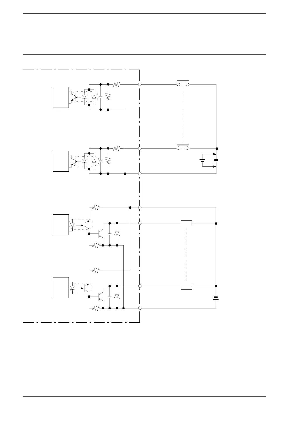
2.3.2.2 PNP Open Collector Type (C16P/C16CP/C32P/C32CP)
FP0-C16P/C16CP/C32P/C32CP
X0
Xn
COM
Y0
(+)
Yn
Load
Load
5.6 k
Ω
5.6 k
Ω
Internal
circuit
Input side
Output side
Internal
circuit
Internal
circuit
Internal
circuit
(-)
24 V DC
(Load voltage and
external power
supply)
(*
Note 1)
24 V DC
(
*
Note 2)
(*
Note 1)
.
Notes
D
(
*
1): The resistor in the control unit is 2 k
•
for X0 through X5,
and 1 k
•
for X6 through XF.
D
(
*
2): Either positive or negative polarity is possible for the input
voltage supply.
 Loading...
