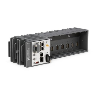
Figure 9. Cabling Clearance
Note The various connector types on C Series modules require different cabling
clearances. For a complete list of cabling clearances for C Series modules, visit
ni.com/info and enter the Info Code crioconn.
Figure 10. Ambient Temperature Measurement Location
1 2 3
4 5 6 7 8
38.1 mm
(1.50 in.)
63.5 mm
(2.50 in.)
63.5 mm
(2.50 in.)
38.1 mm
(1.50 in.)
63.5 mm
(2.50 in.)
63.5 mm
(2.50 in.)
1
1
1
1
1. Measure the ambient temperature here.
Dimensions
The following dimensional drawings apply to all cRIO-905x controllers. For detailed
dimensional drawings and 3D models, visit ni.com/dimensions and search for the model
number.
NI cRIO-905x User Manual | © National Instruments | 21
 Loading...


