action you want the trigger to cause. The cRIO controller supports internal software triggering,
external digital triggering, analog triggering, and internal time triggering.
Analog output supports two different triggering actions: AO Start Trigger and AO Pause
Trigger. An analog or digital signal can initiate these actions. C Series parallel digital input
modules and the controller’s integrated PFI trigger line can be used in any controller slot to
supply a digital trigger. An analog trigger can be supplied by some C Series analog modules.
Refer to the AO Start Trigger Signal and AO Pause Trigger Signal sections for more
information about the analog output trigger signals.
Analog Output Timing Signals
The cRIO controller features the following AO (waveform generation) timing signals:
• AO Sample Clock Signal*
• AO Sample Clock Timebase Signal
• AO Start Trigger Signal*
• AO Pause Trigger Signal*
Signals with an * support digital filtering. Refer to the PFI Filters section for more
information.
AO Sample Clock Signal
The AO sample clock signals when all the analog output channels in the task update. AO
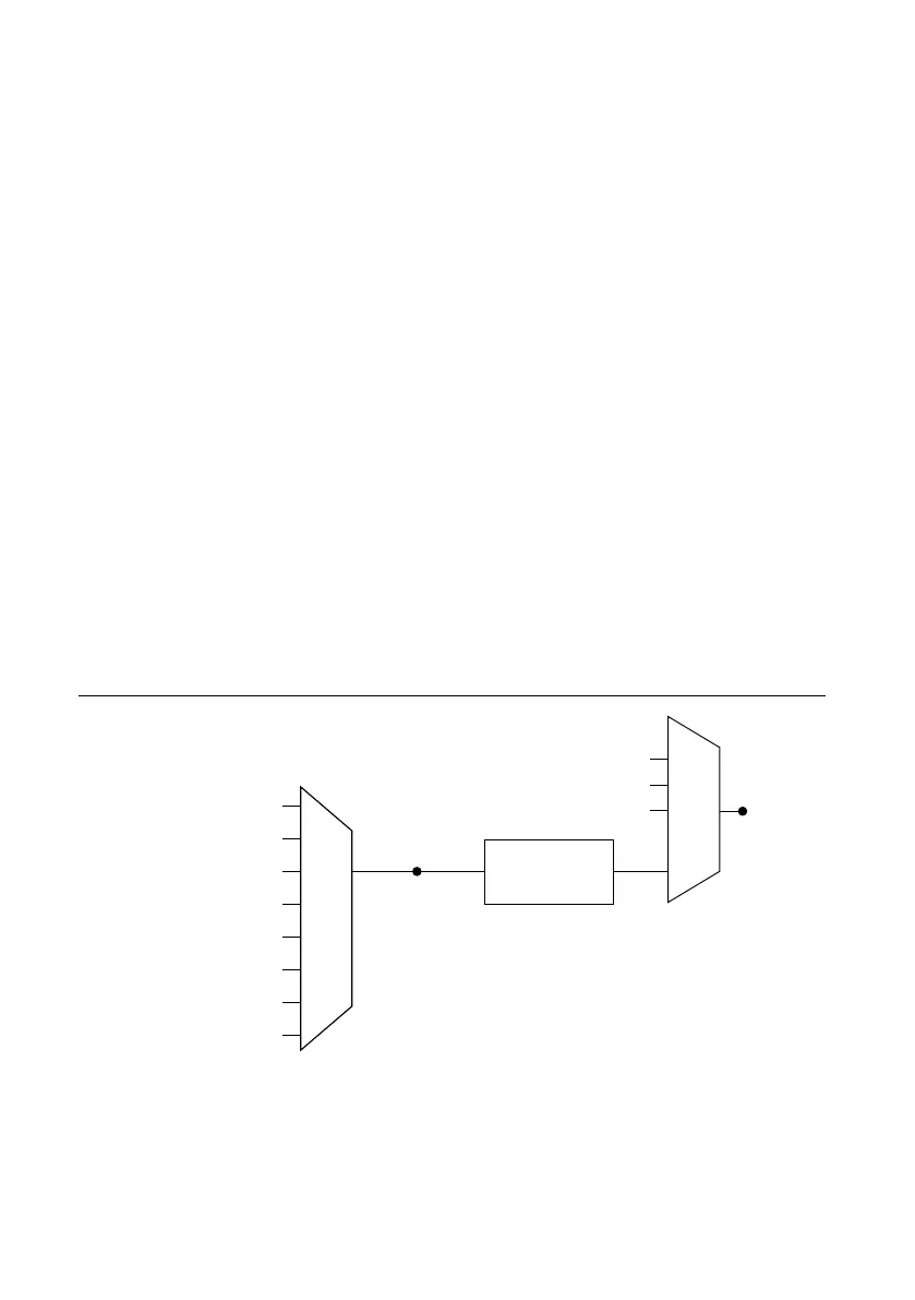
Sample Clock can be generated from external or internal sources as shown in the figure below.
Figure 37. Analog Output Timing Options
Programmable
Clock
Divider
AO Sample Clock
Timebase
PFI
Analog Comparison Event
Ctr n Internal Output
Sample
Clock
Analog Comparison
Event
80 MHz Timebase
20 MHz Timebase
PFI
13.1072 MHz Timebase
12.8 MHz Timebase
10 MHz Timebase
100 kHz Timebase
Routing AO Sample Clock to an Output Terminal
You can route AO Sample Clock to any output PFI terminal. AO Sample Clock is active high
by default.
NI cRIO-905x User Manual | © National Instruments | 47

 Loading...


