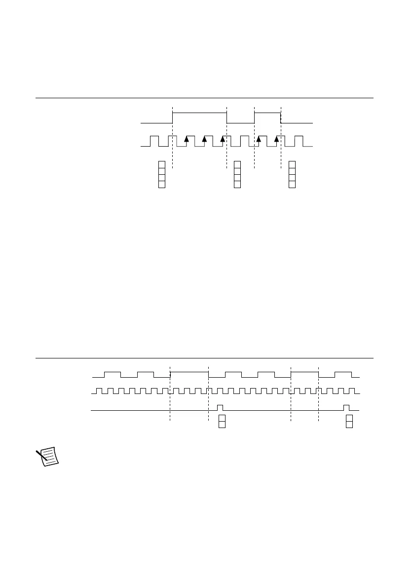
The counter counts the number of edges on the Source input while the Gate input remains
active. On each trailing edge of the Gate signal, the counter stores the count in the counter
FIFO. The sampled values will be transferred to host memory using a high-speed data stream.
The following figure shows an example of an implicit buffered pulse-width measurement.
Figure 55. Implicit Buffered Pulse-Width Measurement
SOURCE
GATE
Counter Value
Buffer
10 3
3 2
212
3
3
2
Sample Clocked Buffered Pulse-Width Measurement
A sample clocked buffered pulse-width measurement is similar to single pulse-width
measurement, but buffered pulse-width measurement takes measurements over multiple pulses
correlated to a sample clock.
The counter counts the number of edges on the Source input while the Gate input remains
active. On each sample clock edge, the counter stores the count in the FIFO of the last pulse
width to complete. The sampled values will be transferred to host memory using a high-speed
data stream.
The following figure shows an example of a sample clocked buffered pulse-width
measurement.
Figure 56. Sample Clocked Buffered Pulse-Width Measurement
Pulse
Source
Sample Clock
2
3
4 2
4
3
2
2
4
Buffer
Note If a pulse does not occur between sample clocks, an overrun error occurs.
For information about connecting counter signals, refer to the Default Counter/Timer Routing
section.
NI cRIO-905x User Manual | © National Instruments | 71

 Loading...


