1. Prepare the surface for mounting the cRIO-905x using the Surface Mounting Dimensions.
2. Align the cRIO-905x on the surface.
3. Fasten the cRIO-905x to the surface using the M4 screws appropriate for the surface.
Note Screws must not exceed 8 mm of insertion into the cRIO-905x. Tighten
the screws to a torque of 1.3 N · m (11.5 lb · in.).
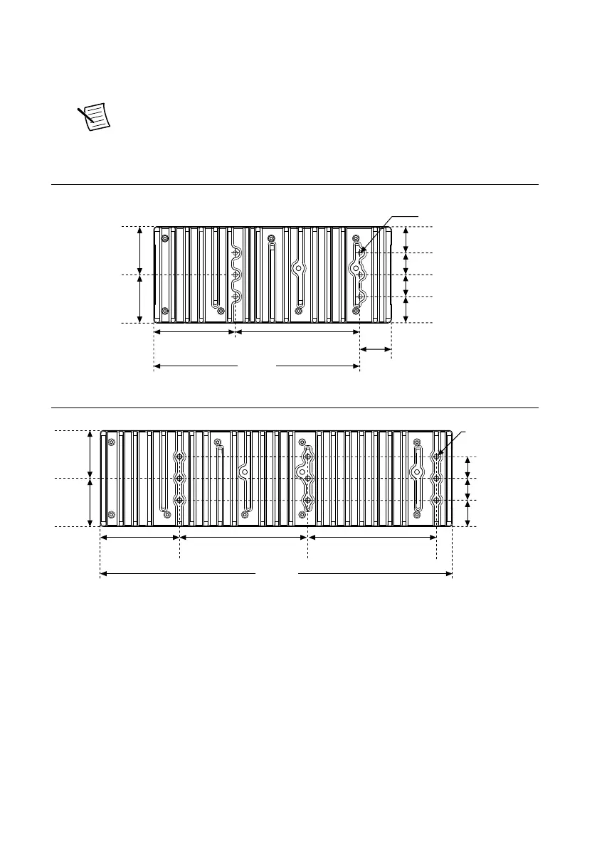
Surface Mounting Rear Dimensions
Figure 20. 4-slot cRIO-905x Rear Dimensions
6x M4 x 0.7
8.0 mm (0.315 in.)
Max Insertion Depth
38.79 mm
(1.527 in.)
24.48 mm
(0.964 in.)
24.49 mm
(0.964 in.)
20.33 mm
(0.800 in.)
20.32 mm
(0.800 in.)
50.82 mm
(2.001 in.)
75.89 mm
(2.988 in.)
116.54 mm
(4.588 in.)
221.4 mm
(8.72 in.)
29 mm
(1.142 in.)
Figure 21. 8-slot cRIO-905x Rear Dimensions
328.6 mm
(12.94 in.)
120 mm
(4.72 in.)
24.5 mm
(0.96 in.)
20.3 mm
(0.80 in.)
20.3 mm
(0.80 in.)
9x M4 x 0.7
8.0 mm (0.32 in.)
Max Insertion Depth
38.8 mm
(1.52 in.)
50.8 mm
(2.00 in.)
73.8 mm
(2.91 in.)
120 mm
(4.72 in.)
Mounting the Controller on a Panel
What to Use
• cRIO-905x
• Screwdriver, Phillips #2
NI cRIO-905x User Manual | © National Instruments | 27

 Loading...


