13
Nautilus® Pro Series Elliptical Assembly Manual
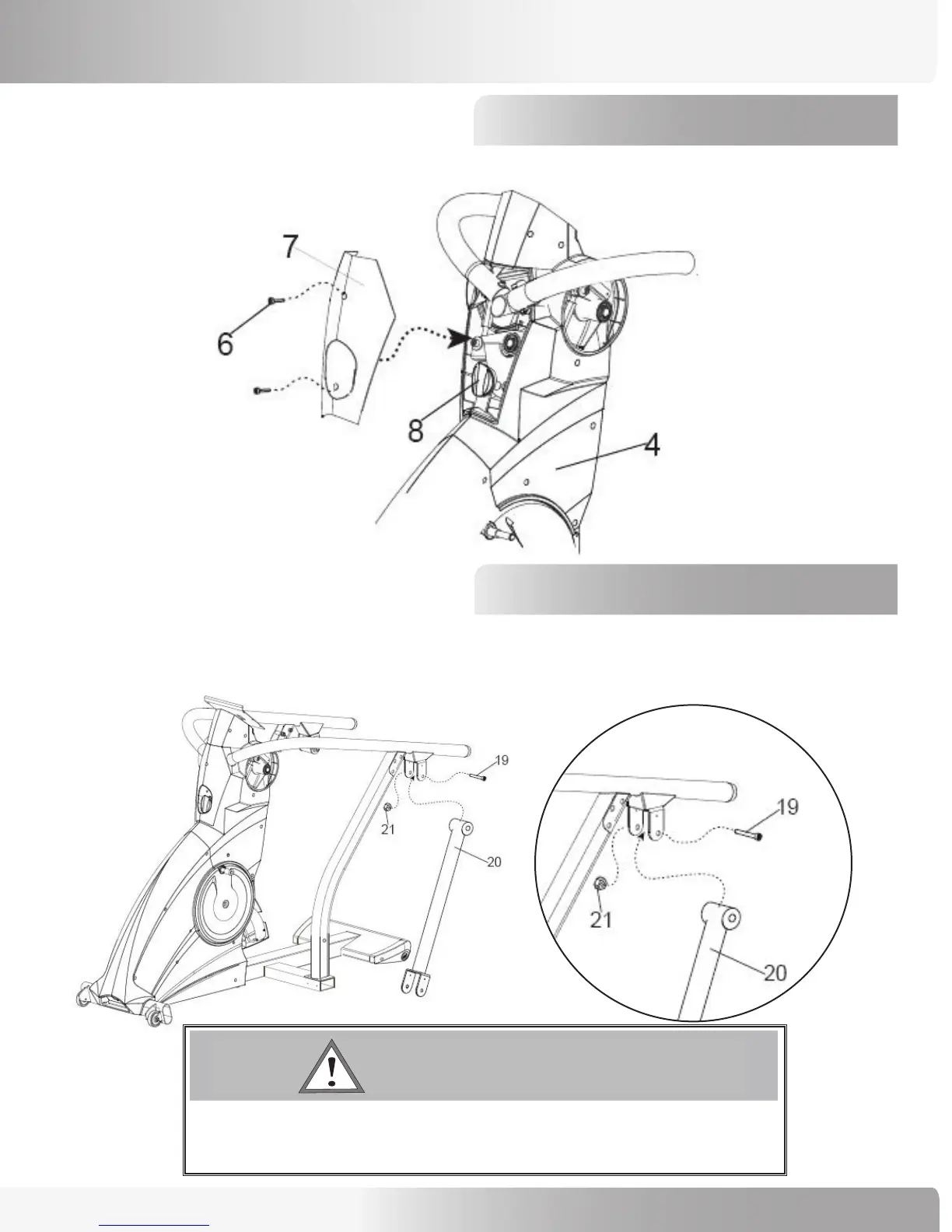
Step 5: Attach Linkage Cover
ASSEMBLY PROCESS
5-1 Use (2) 15mm Phillips Head Screws (Ref #6) to attach the Linkage Cover (#7) to the Base Unit (#4).
Reattach the Lockout Knob (#8).
Base Unit
Linkage Cover
Swing Arm
Side Rail
6-1 Cut wire ties from the top of the swing arm prior to using (2) M12 x 100mm Allen Head Bolts (Ref #19) and
(2) M12 Locking Nuts (ref #21) to attach the Left and Right Swing Arms (#20) to the Side Rails (#9). Tightend
bolts to 36 FT/LBS (500 KG/CM).
7 ! 2 . ) . '
! 4 4 % . 4 ) / .
$ ! . ' % 2
)--%$)!4%!#4)/.2%15)2%$
# ! 5 4 ) / .
BOLT #19 MUST BE TIGHTENED TO 36 FT/LBS (500 KG/CM)
BEFORE PROCEEDING TO THE NEXT STEP.
Step 6: Attach Swing Arms