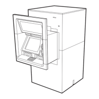
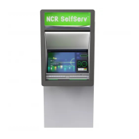
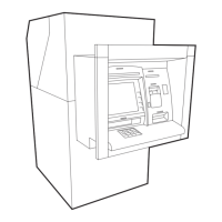
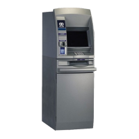
NCR SelfServ 34 ATM Installation Guide
B006-6590-C000 35
5. Fit an appropriate P-clamp (dependant on the diameter of the cable), around the
stripped section of each cable which requires grounding, and attach them to one of the
raised forms on the I/O panel using an M4 x 10 thread forming screw.
Note 1: The screws and P-clamps are packed in a plastic bag attached to the PC
module chassis.
Note 2: If the cable has not been stripped, refer to the instructions in the publication,
NCR SelfServ 32, 34, 38 Site Preparation Requirements (B006-6670).
6. Attach all the clamps to the raised forms on the I/O panel, even if some are not used -
they may be required at a later date.
7. Connect the appropriate cables to the matching connectors on the I/O panel.
8. To connect RS-232 (9 pin), High Order Communication and Ethernet cables, you will
need to access the harness channel frame. To do this, proceed as follows:
a Open the ATM top-box door. Remove and retain the screws securing the door to
the ATM and then remove the door.
b Remove and retain the screws securing the left-hand side panel to the ATM, then
remove the panel to access the harness channel.
M4 Thread Forming Screw
P Clamp