Before Your Start Cabling
DS1000 Hardware Manual Section 2: Trunk and Extension Cabing ◆ 2-1
2
Section 2: Trunk and
Extension Cabling
Before Your Start Cabling
Before You Start Cabling
Reviewing the Installation Method
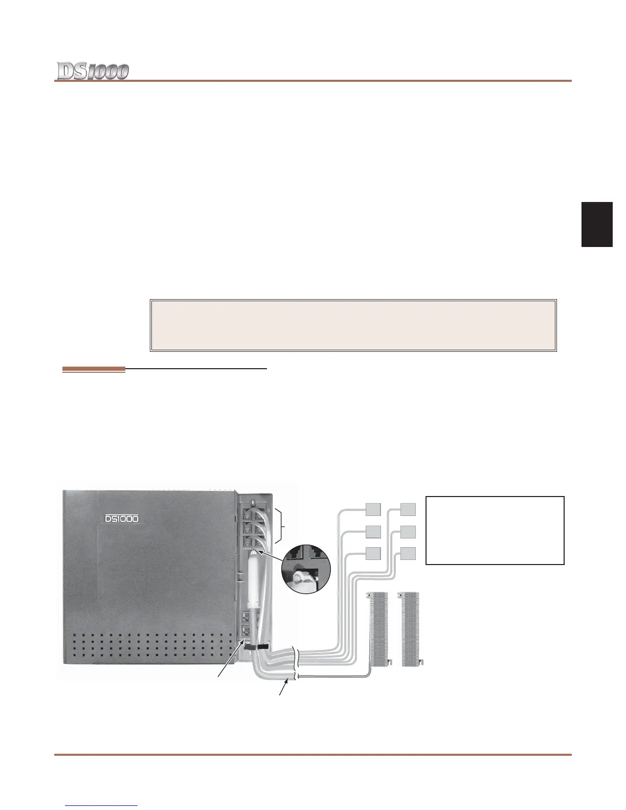
Your system uses a different installation method for trunk/AUX connections and extensions (Figure 2-1):
● Trunk/AUX Mod Jacks
You’ll use up to 6 mod jacks for the trunk/AUX connections. Your telco normally provides trunks in
RJ-11C, RJ-14C, or RJ-25C modular jacks.
● Extension Blocks
The system uses a 66M1-50 extension block and a second 66M1-50 cross connect block for connecting
digital and analog extensions.
!! Important !!
• Install telephones connected to the Main Equipment Cabinet as on-premise extensions only.
• Do not plug in the 25-pair extension cable with power applied.
Figure 2-1: Installation Layout
Cross
Connect
Block
6-Conductor
RJ-11X Plugs
25 Pair
Cable
Extension
Block
80200 - 8
PTF/MDAUDIO
DOOR1
CO 1-3
X10
RS 232
CO 4-6
DOOR2
Trunk/AUX
RJ-25C Jacks
CO 4-6
DOOR
BOX 2
PFT
MDM
RS-232
CO 1-3
AUDIO
DOOR
BOX 1
Notes:
• The system will respond to telco ring signal
in the range of 42-103 VAC @ 20 Hz.
• Telco battery must be 44-56 VDC.
• Turn to Section 4, Optional Equipment for
more on Connecting Door Boxes, Paging,
Power Failure, and 2-OPX Modules.