System Preparation and Configuration
DS1000 Hardware Manual
Section 1: Installation Basics
◆
1-3
1
System Load Factor Calculations
The combination of extensions, 2-OPX Modules, and DSS Consoles you can connect to your system may be
limited by the System Load Factor. Use the
DS1000 System Load Factor Calculations
chart to verify your
system’s configuration.
To check your system configuration:
1. Indicate the quantity for each item installed in the
Qty
column.
2. For each item, multiply the
Qty
times the
Load Factor
and enter the value in
Total Load
.
3. Add all the values in the
Total Load
column and enter the value in
Item
1
.
4. Compare the entry in
Item
2
to your entry in
Item
1
.
Item
1
must always be equal to or less than the
entry in
Item 2.
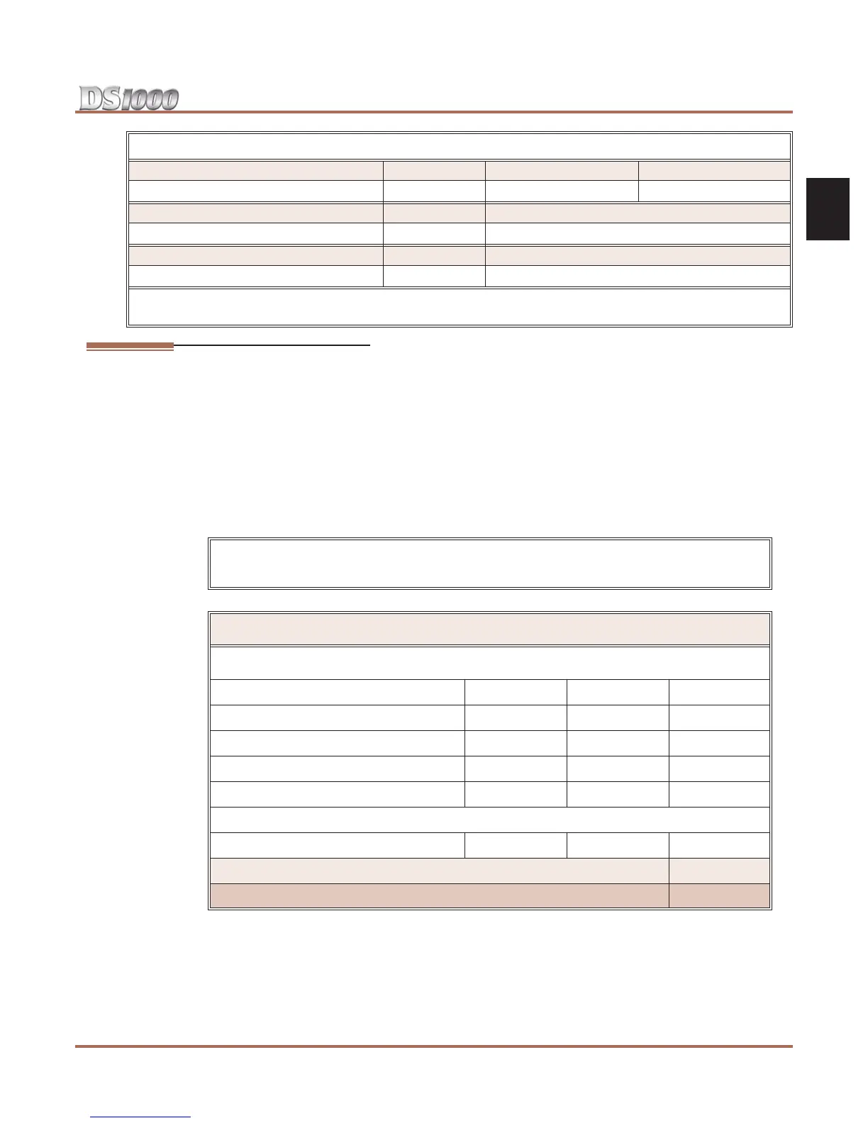
Voice Mail Ports Ports Station Numbers Extension Numbers
-
201-208 500-507
UCD Groups Total Groups UCD Group Master Extension Numbers
8 700-707
Ring Groups Total Groups Ring Group Master Extension Numbers
8 600-607
1
Available for digital station port secondary station numbers. These are used for the second channels on 2-OPX
Modules and Digital VANGARD Voice Mail.
Do not operate your system if the System Load Factor total (Item 1) exceeds the
allowable load of 30 (Item 2).
DS1000 System Load Factor Calculations
Description Load Factor Qty Total Load
Digital Telephone 1
Analog Telephone 1
Analog Door Box 0
24-Button DSS Console 1
110-Button DSS Console 2
Total DSS Consoles installed cannot exceed 4
2-OPX Module 3
Item 1: Total load for this configuration
Item 2: Maximum allowable load 30
Default Numbering