Trunk and AUX Mod Jacks
2-2 ◆ Section 2: Trunk and Extension Cabling DS1000 Hardware Manual
Trunk and AUX Mod Jacks
Installing Trunk and AUX Mod Jacks
To connect to mod jacks:
1. Arrange your mod jacks trunk according to Figure 2-1 Installation Layout on page 2-1.
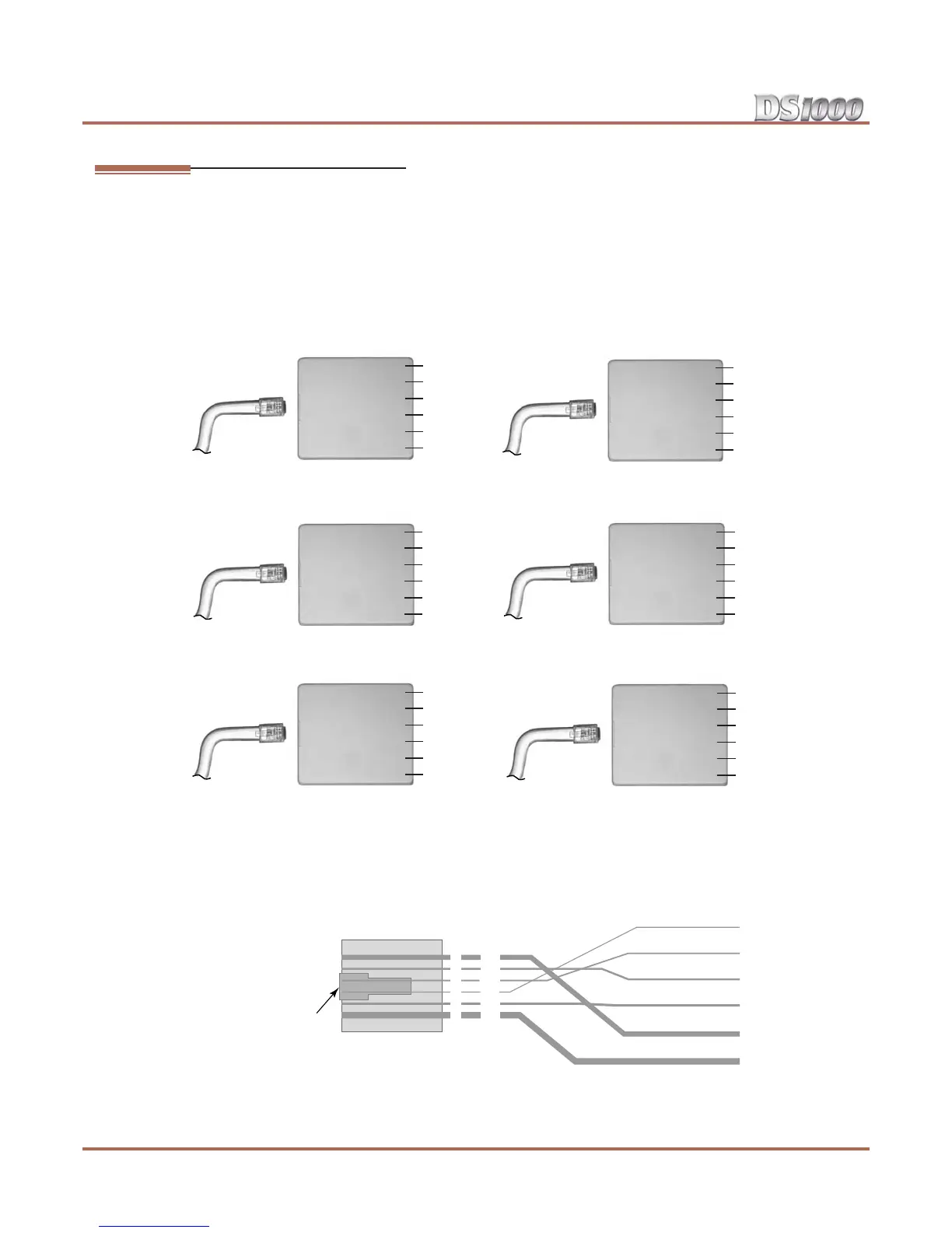
2. Using standard 6-conductor line cords, connect each mod jack to the appropriate plug in the Main
Equipment Cabinet. See Figure 2-2 Mod Jack Assignments below.
3. Figure 2-3 Mod Plug Pinouts below shows the pinouts for each mod jack.
Figure 2-2: Mod Jack Assignments
Figure 2-3: Mod Plug Pinouts
WHT
BLK
RED
GRN
YEL
BLU
CO 1-3
3T
2T
1R
1T
2R
3R
WHT
BLK
RED
GRN
YEL
BLU
Audio
NC
Music T
Page R
Page T
Music R
NC
WHT
BLK
RED
GRN
YEL
BLU
Door Box 2
*
WHT
BLK
RED
GRN
YEL
BLU
CO 4-6
*
6T
5T
4R
4T
5R
6R
WHT
BLK
RED
GRN
YEL
BLU
Door Box 1
NC
Relay 1T
DB 1R
DB 1T
Relay 1R
NC
WHT
BLK
RED
GRN
YEL
BLU
PFT/MDM
NC
NC
PFT/MDM R
PFT/MDM T
NC
NC
80200 - 9C
NC
Relay 2T
DB 2R
DB 2T
Relay 2R
NC
*
*
*
*
*
*
*
*
*
*
*
*
*
Requires Expansion Board
RJ-25C
Pin
Latch
faces up
6-Pin
Mod Jack
Port
Designation
WHT-BLU (1T)
BLU-WHT (1R)
WHT-ORN (2T)
ORN-WHT (2R)
WHT-GRN (3T)
GRN-WHT (3R)
80200 - 10
3T
2T
1R
1T
2R
3R
1
2
3
4
5
6