2-OPX Module
4-10 ◆ Section 4: Optional Equipment DS1000 Hardware Manual
2-OPX Module
Installing the 2-OPX Module
The 2-OPX Module (P/N 92177A) provides two 2500 type analog circuits for connection to on-premise
2500 type single line devices (i.e., telephones, fax machines, modems, etc.) and to telco OL13B/C OPX cir-
cuits. It uses a single digital extension circuit for the power and signaling for both analog ports.
Note: The 2-OPX Module is a discontinued item, but you may find it at some installation sites.
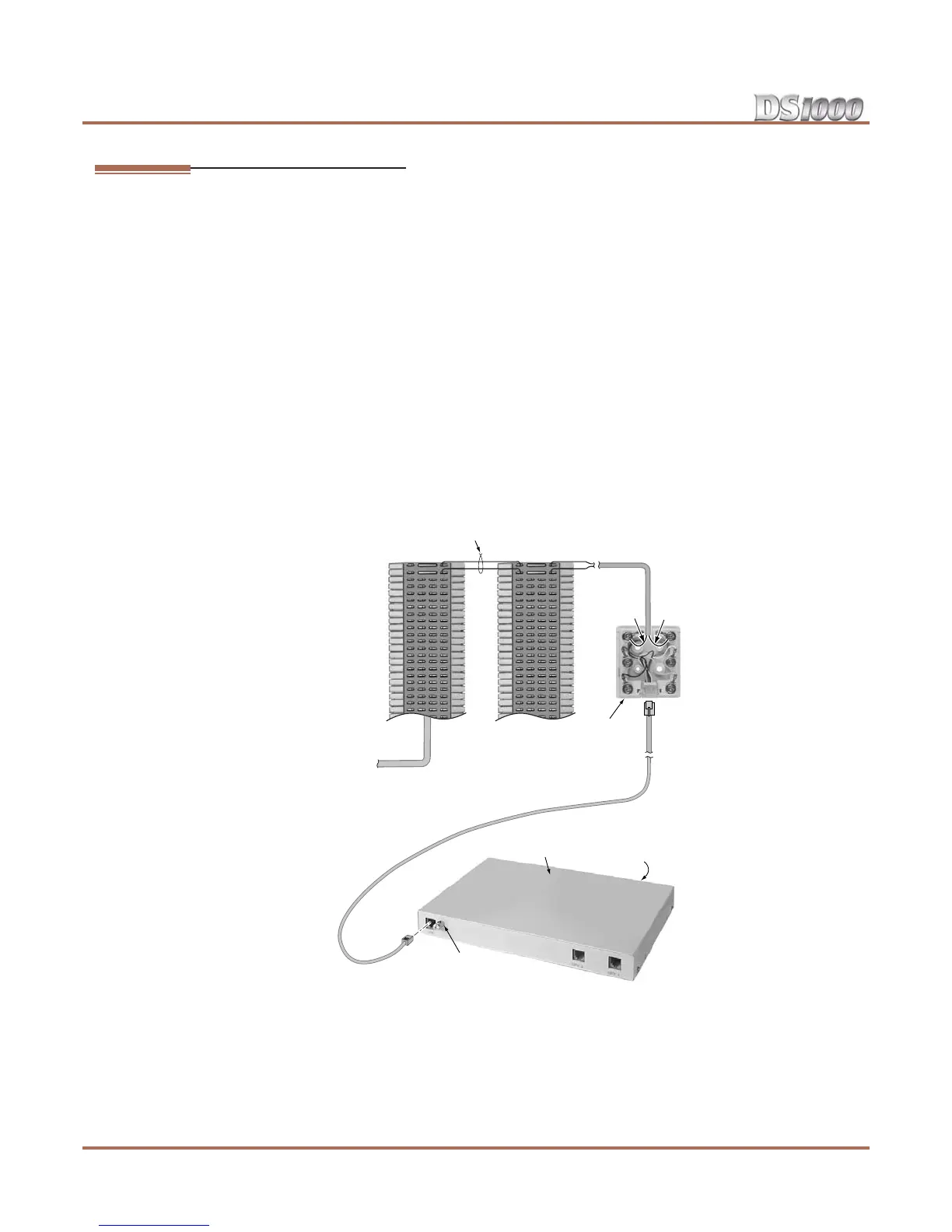
To install a 2-OPX Module (Figure 4-7):
1. Install a modular jack for the 2 OPX Module within six feet of the module’s location.
2. Run one-pair 24 AWG station cable from the cross-connect block to the modular jack.
3. Terminate the station cable WHT/BLU - BLU/WHT leads to the RED and GRN lugs in the modular jack.
4. Back at the main equipment location, run one pair of cross-connect wire between the pins on the exten-
sion block and cross-connect block to complete the connection.
5. Install bridging clips as required.
6. Ground the 2-OPX Module by connecting a 14 AWG ground wire from the FG lug on the module to a
known earth ground.
7. Plug a line cord into the 2-OPX unit and the 2-OPX’s modular jack.
The DS1 LED on the 2-OPX Module lights steadily.
Figure 4-7: Connecting the 2-OPX Module
80000 - 41A
BLK YEL
GRN RED
Station
Block
Cross
Connect
Block
14 AWG from
FG lug to known
Earth Ground
BLU-WHTWHT-BLU
625
Modular
Jack
One-Pair Cross-Connect
2-OPX Module
DS1
FG