Connecting Extensions
3-2 ◆ Section 3: Connecting Trunks and Extensions DS1000 Hardware Manual
Connecting Extensions
Connecting Analog and Digital Extensions
The base system connects 8 digital extensions and 4 analog extensions. With the Expansion Board installed,
the system provides a total of 16 digital extensions and 8 analog extensions.
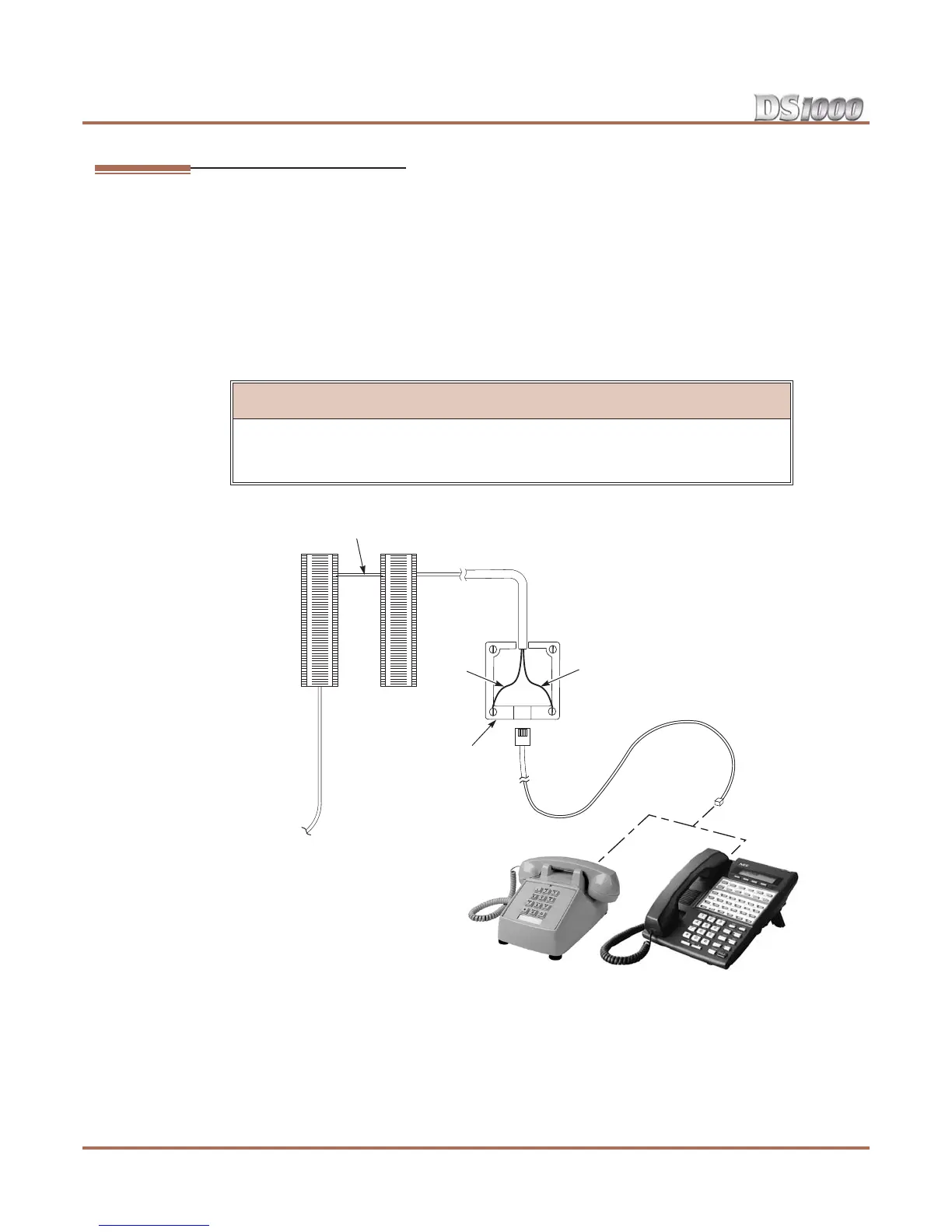
To connect extensions (Figure 3-2):
1. Install a modular jack for each extension within 6 feet of the telephone’s location.
2. For each extension, run one-pair 24 AWG station cable from the cross-connect block to the modular jack.
3. Terminate the station cable WHT/BLU - BLU/WHT leads to the RED and GRN lugs in the modular jack.
4. Back at the main equipment location, run one pair of cross-connect wire between the pins on the exten-
sion block and cross-connect block to complete the connection.
5. Install bridging clips as required.
!! Important !!
Digital station ports (300-315) automatically detect the type of connected keyset when
you plug it in. You don’t have to individually set keyset circuit types in 1801 - Exten-
sion Circuit Type.
Figure 3-2: Connecting Extensions
625
Modular
Jack
BLK
YEL
RED
GRN
BLU-WHT
WHT-BLU
Cross
Connect
Block
One-Pair
Cross Connect
Station
Block
80200 - 11