System Board Layout 4-3
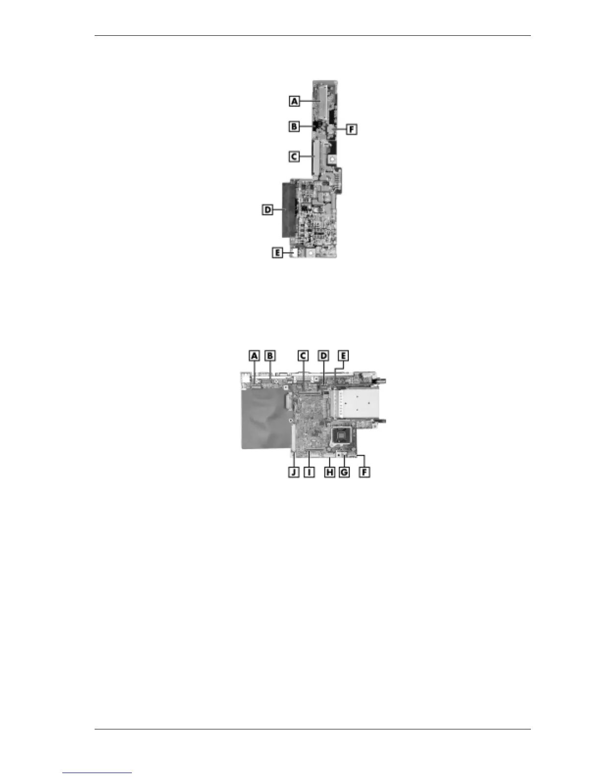
I/O Board Connectors
A – Keyboard Cable Connector P5 D – Hard Disc Drive Connector P2
B – Main Board Connector P3 (back side) E – CMOS Battery Cable Connector P1
C – Diskette Drive Cable Connector P6 F – VersaGlide Cable Connector P8
Main Board Connectors
A – CD Control Board Connector P18 F – Connector P4 (not used)
B – LCD Panel Connector P15 G – CPU Fan Cable Connector P5
C – DC/DC Board Connector P10 H – Audio Board Connector P7
D – LED Board Connector P8 I – DC/DC Board Connector P9
E – PC Card Assembly Connector P2 J – I/O Board Connector P12
On the back side of the main board are connectors P22, P26, and P27 and DIP switches S2, S3,
and S4. (See “DIP Switch Settings” in Chapter 2 for a description of the DIP switches.)
Connector P22 is for connecting an optional LAN, modem, or combination LAN/modem Mini-
PCI board. Connectors P26 and P27 are for connecting a Mini-PCI board that is used in
conjunction with the LAN or modem board.
These connectors and DIP switches are accessible by removing the PCI LAN/modem card bay
cover from the bottom of the system.