Disassembly and Reassembly 3-11
5.
Partially lift the heat plate. Unplug the processor fan cable from connector P5 on the main
board and remove the heat plate.
6.
Release the keyboard cable from connector P5 on the I/O board by pushing the two lock
tabs (one on each side) away from the connector. Remove the keyboard.
Top Cover
Remove the top cover as follows.
1.
Remove the battery pack, hard disk drive, LCD panel, keyboard, and heat plate from the
system.
2.
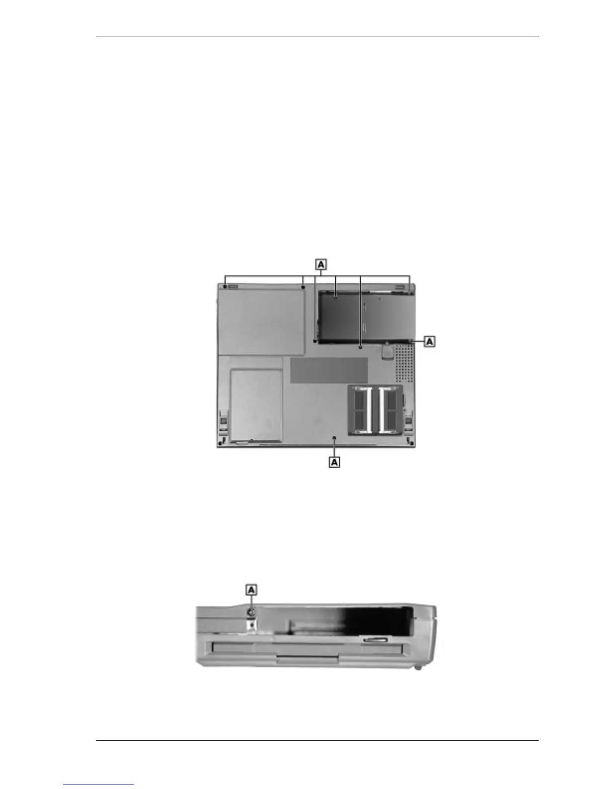
Remove the eight screws on the bottom that partially secure the top cover to the system.
Note that the three screws in the battery compartment are shorter than the other five screws.
Removing the bottom screws
A – Screws (8)
3.
Turn the system over.
4.
Locate and remove the screw inside the hard disk drive bay that secures the top cover.
Removing the drive bay screw
A – Screw