Data
Port Protocol
alarm determine the voltage between these pins. The nurse call
polarity is set by using the procedures in the
Start-up
and
Use
section. To access the nurse call menu from the main menu,
press
softkeys SETUP, NEXT, NEXT and NCALL.
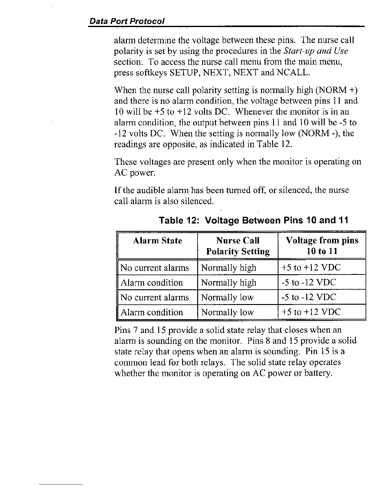
When the nurse call polarity setting is normally high (NORM
+)
and there is no alarm condition, the voltage between pins 11 and
10 will be
+5
to +12 volts DC. Whenever the monitor is in an
alarm condition, the output between pins 11 and 10 will be
-5
to
-12 volts
DC.
When the setting is normally low (NORM
-1,
the
readings are opposite, as indicated in Table 12.
These voltages are present only when the monitor is operating on
AC power.
If the audible alann has been turned off, or silenced, the nurse
call alarm is also silenced.
Table
12:
Voltage Between Pins
10
and
11
Pins
7
and
15
provide a solid state relay that closes when an
alarm is sounding on the monitor. Pins
8
and
15
provide a solid
state relay that opens when an alarm is sounding. Pin 15 is a
coimnon lead for both relays. The solid state relay operates
whether the monitor is operating on AC power or battery.