N723-EA Hardware User Guide
Chapter 5 Application Interfaces
Copyright © Neoway Technology Co., Ltd. All rights reserved.
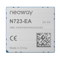
Figure 5-1 Voltage drop of the power supply.
Min: 3.4V
VBAT
Burst
Burst
VBAT≥3.4V
Drop
Never use a diode to make the drop voltage between a higher input and module power. The forward voltage drop
V
f
of the diode has two characteristics: one is that it increases with the increase of forward current; the other is
that it increases significantly at a low temperature. If there is an instantaneous high current, the instantaneous
increase of forward voltage drop will lead to unstable operating voltage of the module, or even damage the
module.
The power supply design of the N723-EA module is determined by the power input voltage. The
designs are classified by power input voltage as follows:
⚫
Supports the 3.4V - 4.2 V power input (typical value: 3.8 V, using the battery for power supply)
⚫
Supports the 4.2V - 5.5 V power input (typical value: 5.0 V, using the internal rectifier of the
computer for power supply)
⚫
Supports the 5.5 V - 24 V power input (typical value: 12 V, typically applicable to the automobile
industry)
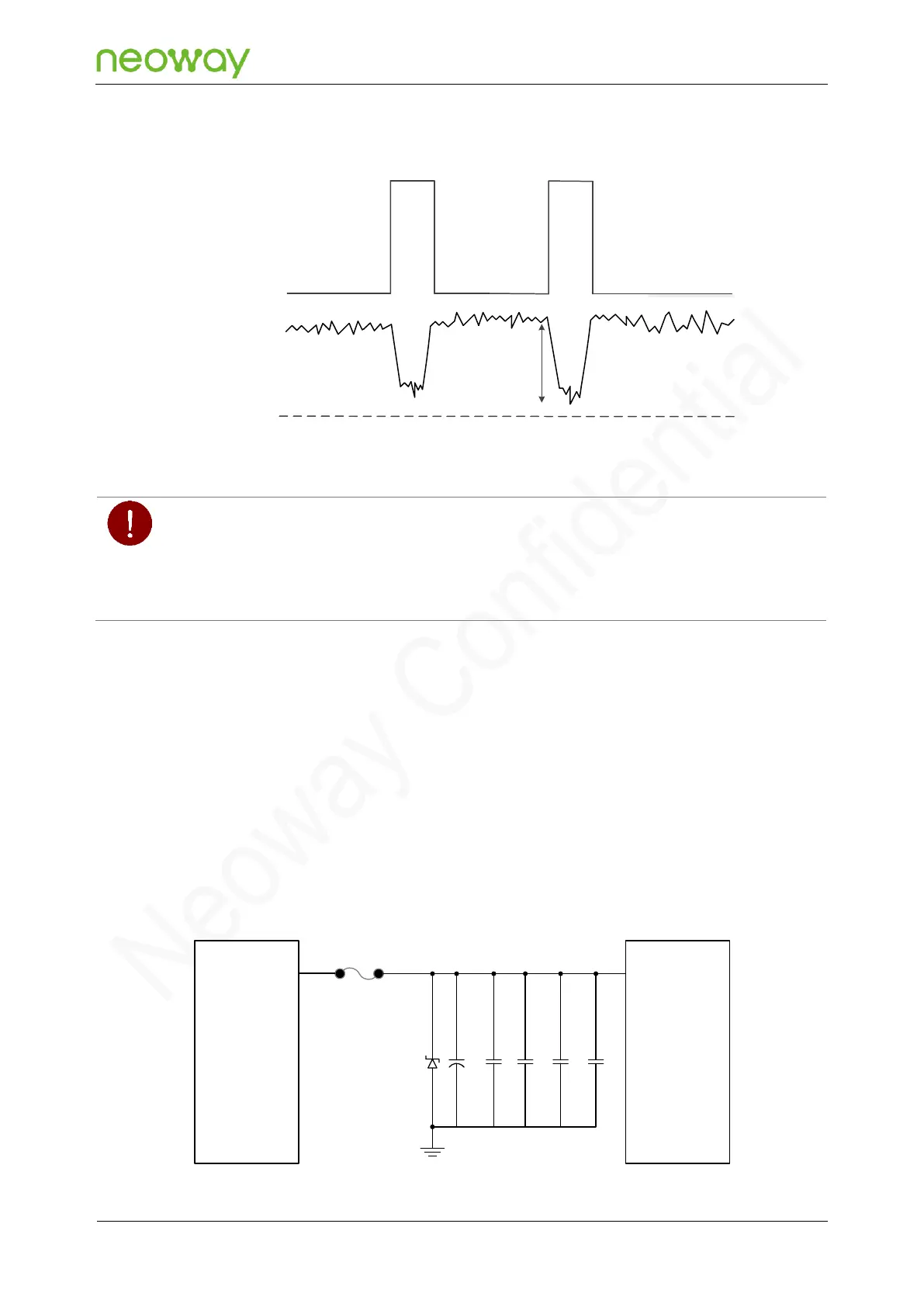
The recommended 3.4V to 4.2 V input design is as follows:
Figure 5-2 Recommended design 1
N723-EA
Module
Power Supply
D1
C1 C2 C3 C4 C5
Test point
I_max
100μF 10μF 100pF 33pF 0.1μF
VBAT
TVS