EasyManua.ls Logo

Neoway N723-EA - Figure 5-21 Recommended Level Shifting Circuit 2

Neoway N723-EA
75 pages
Print Icon
To Next Page IconTo Next Page
To Previous Page IconTo Previous Page
Loading...
N723-EA Hardware User Guide
Chapter 5 Application Interfaces
Copyright © Neoway Technology Co., Ltd. All rights reserved.
43
Figure 5-21 Recommended level shifting circuit 2
UART_TXD
VDD_1P8
10kΩ
R3
Q1
4.7kΩ
R1
22kΩ
R2
10kΩ
R4
10pF
C1
10pF C2
100kΩ
R5
Q2
4.7kΩ
R6
VCC_IO
MCU_RXD
MCU_TXD
VDD_1P8
Q4
10kΩ
R10
10kΩ
R9
10pF C4
10pF C3
Q3
UART_RXD
100kΩ
R12
100kΩ
R11
10kΩ
R8
4.7kΩ
R7
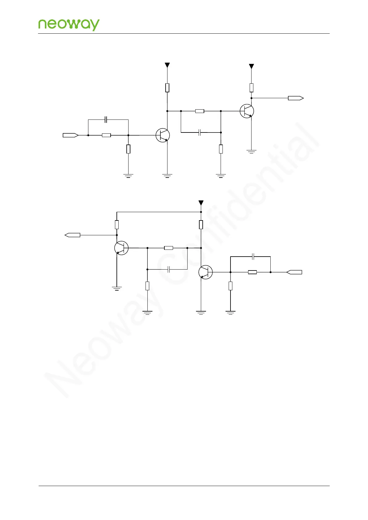
PCB design guideline:
Q1/Q2: MMBT3904 or MMBT2222 High-speed transistors are better.
MCU_TXD and MCU_RXD are the sending and receiving ports of the MCU respectively,
and TXD and RXD are the sending and receiving ports of the module respectively. VCC_IO
is the IO voltage of the MCU. VDD_1P8 is the IO voltage of the module.
If the serial port baud rate is less than or equal to 115200 bps, designing the CTS and RTS
circuit by referring to recommended level shifting circuit 3 is recommended. As shown in Figure
5-22.

Table of Contents