N723-EA Hardware User Guide
Chapter 5 Application Interfaces
Copyright © Neoway Technology Co., Ltd. All rights reserved.
⚫
It is prohibited to use diodes for level shifting.
If the UART does not match the logic voltage of the MCU, add a level shifting circuit outside of the
module. Three level shifting circuits are recommended based on the differences in logic levels and
rates.
⚫
If the serial port baud rate is greater than 115200 bps, it is recommended to refer to the
recommended level shifting circuit 1. See Figure 5-20.
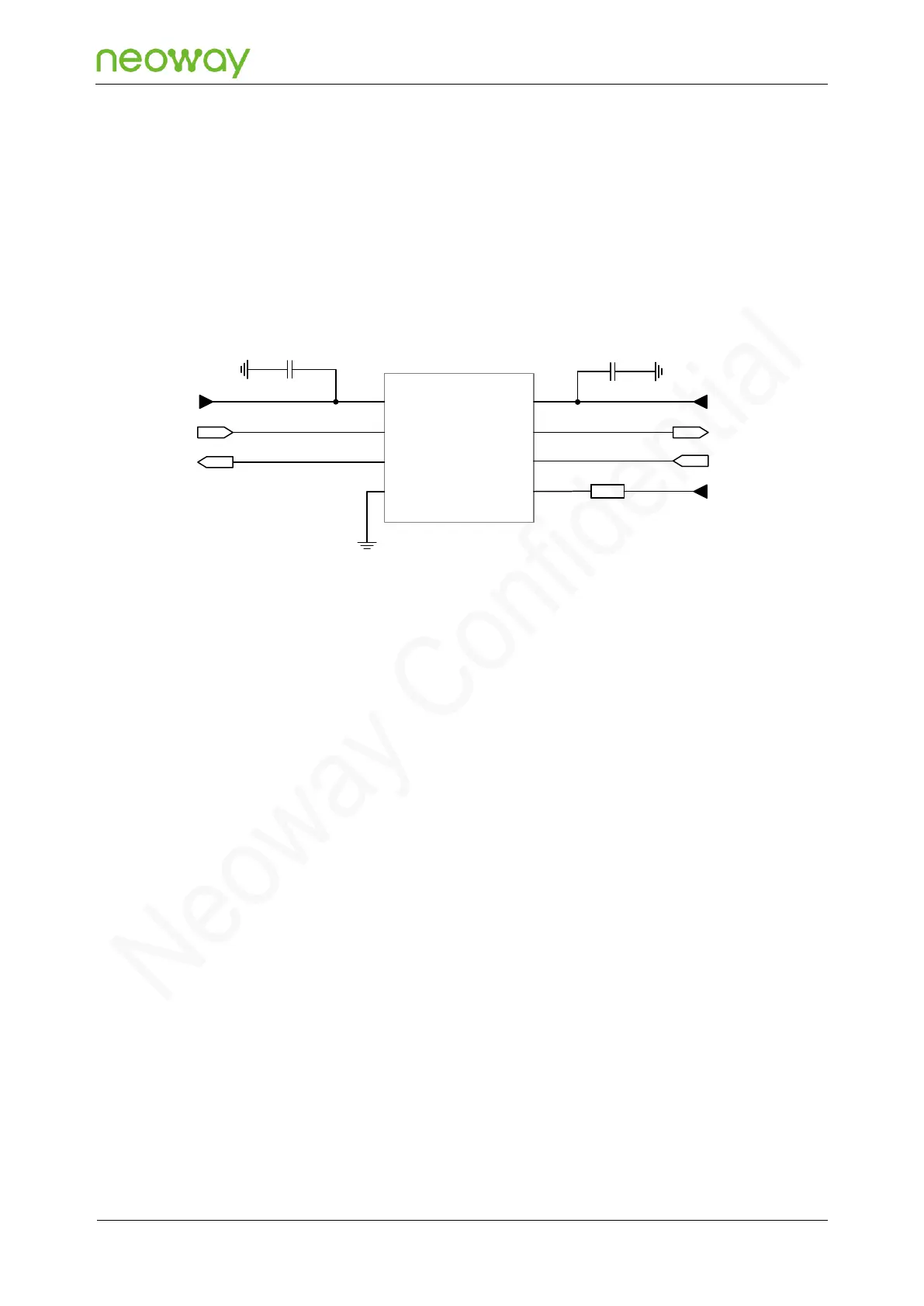
Figure 5-20 Recommended level shifting circuit 1
VL
IO_VL1
IO_VL2
GND
VCC
IO_VCC1
IO_VCC2
EN
VDD_1P8
CP_UART_TXD
CP_UART_RXD
0.1μF
C1
VDD_IO
MCU_UART_RXD
MCU_UART_TXD
VDD_1P8
0.1μF
C2
0Ω
R1
1
2
3
4
8
7
6
5
− VL is the reference voltage of IO_VL1 and IO_VL2.
− VCC is the reference voltage of IO_VCC1 and IO_VCC2.
− EN is the enable pin. In the above circuit, the EN pin is connected to VDD_1P8 and the level
shifter is always working.
⚫
If the serial port baud rate is less than or equal to 115200 bps, designing the serial port TXD and
RXD by referring to recommended level shifting circuit 2 is recommended. As shown in Figure 5-
21.