N723-EA Hardware User Guide
Chapter 5 Application Interfaces
Copyright © Neoway Technology Co., Ltd. All rights reserved.
Used for AT commands
communication and support
hardware flow control.
Leave this pin floating if it is not
used.
The user allows the
module to send data.
The module requests the
user to send data.
Only used for debug.
Leave this pin floating if it is not
used.
Used for data transmission.
Leave this pin floating if it is not
used.
N723-EA provides three UART interfaces, of which the CP_UART interface supports hardware flow
control and a maximum rate of 3.6 Mbps. DEBUG_UART1 only supports for debugging, there will be
Log information output after the module boots up, and the baud rate supports up to 115200 bps. UART2
can be used for data communication of external devices, and the baud rate supports up to 115200 bps.
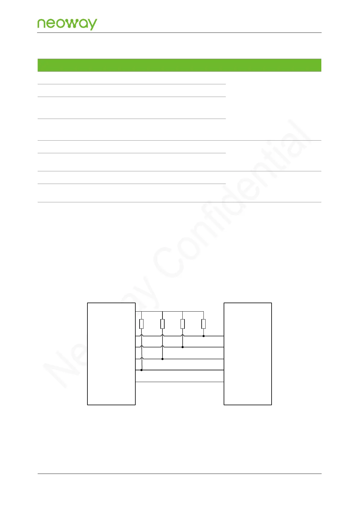
Figure 5-19 shows the reference design of the UART interface. All the UART interfaces of the module
are 1.8 V level.
Figure 5-19 Reference design of the UART connection
Device
N723-EA
Module
CP_UART_TXD
CP_UART_RXD
CP_UART_CTS
CP_UART_RTS
GND
MCU_UART_RXD
MCU_UART_TXD
MCU_UART_RTS
MCU_UART_CTS
GND
4.7kΩ
R4
4.7kΩ
R3
10kΩ
R2
10kΩ
R1
VDD_1P8
Schematic Design Guidelines:
⚫
Pay attention to the corresponding relations between the signal direction and the connection.